Other Parts Discussed in Thread: AWR1843AOPEVM, AWR1843, AWR1843BOOST, AWR1843AOP, AWR1642BOOST
I have an issue of communication with AWR1843AOPEVM through DCA1000EVM over LVDS with mmWave Studio 2.1.1.0.
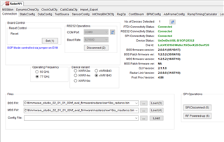
The following screenshots show that a valid connection has been established with the AWR1843 and the DCA1000 board, and the configuration settings for the RF system was also correct as shown through the logs provided. However, once I try to use the "DCA1000 ARM" command, no response is provided by the acquisition board and the LVDS_PATH_ERR_LED3 is turned on, from which I assume there is an issue with the LVDS bus.
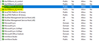
A picture of the switches configuration, is also provided. I followed the AWR1843AOPEVM user guide for DCA1000EVM connections.


LOG:
[15:25:14] [RadarAPI]: ar1.ChanNAdcConfig(1, 1, 0, 1, 1, 1, 1, 2, 2, 0)
[15:25:14] [RadarAPI]: Status: Passed
[15:25:17] [RadarAPI]: ar1.LPModConfig(0, 0)
[15:25:17] [RadarAPI]: Status: Passed
[15:25:17] [RadarAPI]: ar1.RfInit()
[15:25:18] RF Init async event received!
[15:25:18] [RadarAPI]: Time stamp, Temperture: 708139,48; APLL Status, Update: 1, 0; SynthVCO1 Status, Update: 1, 1; SynthVCO2 Status, Update: 1, 1; LODist Status, Update: 1, 1; RxADCDC Status, Update: 1, 1; HPFcutoff Status, Update: 1, 1; LPFcutoff Status, Update: 1, 1; PeakDetector Status, Update: 1, 1; TxPower Status, Update: 1, 1; RxGain Status, Update: 1, 1; TxPhase Status, Update: 1, 1; RxIQMM Status, Update: 1, 1;
[15:25:18] [RadarAPI]: Status: Passed
[15:25:22] [RadarAPI]: ar1.DataPathConfig(513, 1216644097, 0)
[15:25:22] [RadarAPI]: Status: Passed
[15:25:24] [RadarAPI]: ar1.LvdsClkConfig(1, 1)
[15:25:24] [RadarAPI]: Status: Passed
[15:25:26] [RadarAPI]: ar1.LVDSLaneConfig(0, 1, 1, 0, 0, 1, 0, 0)
[15:25:26] [RadarAPI]: Status: Passed
[15:25:31] [RadarAPI]: ar1.ProfileConfig(0, 77, 100, 6, 60, 0, 0, 0, 0, 0, 0, 29.982, 0, 256, 10000, 0, 0, 30)
[15:25:31] [RadarAPI]: Status: Passed
[15:25:31] [RadarAPI]: ar1.ChirpConfig(0, 0, 0, 0, 0, 0, 0, 1, 0, 0)
[15:25:32] [RadarAPI]: Status: Passed
[15:25:33] Test Source Already Disabled...!!!
[15:25:33] [RadarAPI]: ar1.DisableTestSource(0)
[15:25:33] [RadarAPI]: Status: Passed
[15:25:33] [RadarAPI]: ar1.FrameConfig(0, 0, 8, 128, 40, 0, 0, 1)
[15:25:33] [RadarAPI]: Status: Passed
[15:25:39] [RadarAPI]: ar1.GetCaptureCardDllVersion()
[15:25:39] [RadarAPI]: Sending dll_version command to DCA1000
[15:25:40] [RadarAPI]:
[15:25:40] DLL Version : 1.0
[15:25:40] [RadarAPI]: ar1.SelectCaptureDevice("DCA1000")
[15:25:40] [RadarAPI]: Status: Passed
[15:25:43] [RadarAPI]: ar1.CaptureCardConfig_ResetFPGA()
[15:25:43] [RadarAPI]: ar1.CaptureCardConfig_Mode(1, 2, 1, 2, 3, 30)
[15:25:43] [RadarAPI]: ar1.CaptureCardConfig_PacketDelay(25)
[15:25:43] [RadarAPI]: Sending reset_fpga command to DCA1000
[15:25:43] [RadarAPI]:
[15:25:43] Reset FPGA command : Success
[15:25:43] [RadarAPI]: Sending fpga command to DCA1000
[15:25:43] [RadarAPI]:
[15:25:43] FPGA Configuration command : Success
[15:25:43] [RadarAPI]: Sending record command to DCA1000
[15:25:43] [RadarAPI]:
[15:25:43] Configure Record command : Success
[15:25:43] [RadarAPI]: Sending fpga_version command to DCA1000
[15:25:43] [RadarAPI]:
[15:25:43]
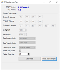
[15:25:43] FPGA Version : 2.8 [Record]
[15:25:43]
[15:26:08] [RadarAPI]: ar1.CaptureCardConfig_StartRecord("C:\\ti\\mmwave_studio_02_01_01_00\\mmWaveStudio\\PostProc\\adc_data.bin", 1)
[15:26:08] [RadarAPI]: Sending start_record command to DCA1000
[15:26:18] [RadarAPI]:
[15:26:18] Start Record :
[15:26:18] Timeout Error! System disconnected
If you have any advice or suggestion on how to test it further, it would be much appreciated.
Thanks in advance.