This thread has been locked.

If you have a related question, please click the "Ask a related question" button in the top right corner. The newly created question will be automatically linked to this question.

Capture raw data using mmWave Studio 2.1

Other Parts Discussed in Thread: IWR6843

Hi ,

we tried to capture raw data using mmwave studio 2.1 for iwr6843 and can able to capture it. But if we change the LVDS lane configuration from lane 2 to lane 1 in the studio 2.1 . we are getting an excessive data . I have attached the configuration images below and the respective frame size image.

Radar configuration:
1. Two Transmitter and Four receiver
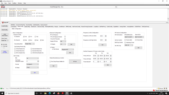
2. ADC Bits : 16 bit
3. ADC Format : complex 1x mode
4. ADC Mode : Regular ADC
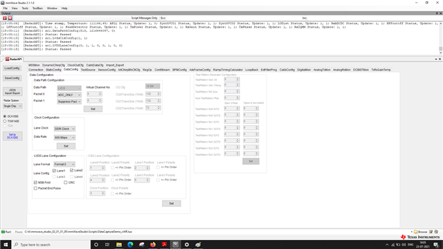
5. Lane clock : DDR Clock
6. Data rate : 600Mbps
7. Lane Format : Format 0
8. Lane config : two lanes(Lane 1 and Lane 2)
9. ADC Samples : 256

Max data size per single Chirp: 256 samples X 4 Rx X 2 IQ X 16 bit / 8 = 4KByte
Data per frame : 4KByte * 128 = 512 KB

Single frame size we got Two lane = 512 kb
Single lane = 1024 kb

how the change in lane in radar affecting the frame size. can u help me to understand it better.

  • Hello Balaji,

    I've forwarded you query to one of our experts here. 

    Please expect a response within two days. 

    Regards,

    Ishita

  • Hi Balaji,

                    The data from RADAR device is sent out on LVDS lanes depending on number of lanes it supports.

    Would recommend having a look at this link and also going through https://www.ti.com/lit/an/swra581b/swra581b.pdf

    There are few devices which may have just one lane or may have 3 lanes too. The mmWave studio allows the capture of the RAW data per user config of number of lanes. However the integrated post processing expects all the supported lanes of the device being used. You can have your own post processing being developed to read RAW data and then according to the number of lanes used to capture the data can process the data.