This thread has been locked.

If you have a related question, please click the "Ask a related question" button in the top right corner. The newly created question will be automatically linked to this question.

IWR6843ISK-ODS: Misreported XYZ data on MMWave demo visualizer - data rotated and split along center

Part Number: IWR6843ISK-ODS
Other Parts Discussed in Thread: IWR6843, IWR6843AOP

After following instructions in CCS under Software/mmWave Sensors/Industrial Toolbox (4.8.0)/Labs/- Out of Box Demo - / 68xx ODS - Point Cloud Demo,
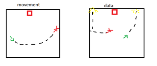
Pointcloud data seen in the demo visualiser seems to be rotated, displaced and split along the center of the sensor. An image attached shows the behaviour of the detected points in relation to the actual target movement.

Sensor also freezes momentarily when the object is right in front of it, which is about when the data jumps from the right to the left of the sensor.

Any Ideas on a fix? Maybe it has something to do with configurations or in the .bin that was flashed.


Thank you.

  • Hi, 

    Can you please let us know the orientation in which the sensor is mounted? 

    Regards, 

    Sudharshan K N 

  • Sensor orientation is like so IIRC

    So the "teleportation" - when the points flip from the right to the left side - occurs around zero azimuth and zero elevation, facing the board directly.

  • Hi, 

    Will check and get back to you. 

    Regards, 

    Sudharshan K N 

  • Hi, 

    Have you selected the device as AOP in the GUI? Because the antenna pattern of ODS and AOP match. 

    Regards, 

    Sudharshan K N 

  • Yes the device was selected as AOP. The pointcloud was represented in 3D in the upper left plot.

    Furthermore, I extracted the live XYZ data with a python TLV parser and the same behaviour was observed.

  • Dear Experts,

    I'm having the same problem and I'm very much interested in solving it! Actually I'm using the AOP version of the IWR6843 but as you've already mentioned they have the same antenna patern. I'm observing exactly the same behavior of the point cloud data as described by Charles Fortier in this thread. 

    I'm using the mmwave_sdk_68xx_aop_hwa (OOB for AOP) project from the 03_05_00_04 SDK on a custom hardware with the IWR6843AOP (ES2.0) and another microcontroller for collecting the point cloud data. I have tried it also with the IWR6843AOP-EVM and the TI Visualizer as well as a Matlab TLV parser. It shows always the same behavior. To me it looks like a wrong calculation of the AoA due to a wrong (virtual) antenna patern. Therefore I checked everthing which is related to the antenne configuartion.

    The tx antennas in the cfg file are configured as:

    channelCfg 15 7 0
    chirpCfg 0 0 0 0 0 0 0 1
    chirpCfg 1 1 0 0 0 0 0 2
    chirpCfg 2 2 0 0 0 0 0 4

    The predefined Symbols in the CCS project are set to

    XWR68XX_AOP_ANTENNA_PATTERN

    USE_2D_AOA_DPU

    which means that due to the defines in the code the right antenna pattern from the antenna_geometry.c files is used as well as the 2DAoA processing from the related dpu.

    Thanks & regards

    Lukas

  • Hi, 

    Thanks for bringing this to the notice? Do you see the same behavior with other demos as well (Ex: 3D people counting)? Please let us know. We will check this internally and get back to you. 

    Regards, 

    Sudharshan K N 

  • Hi,

    today I tried the 3D people counting demo and it seems like it's working as expected. But it's using a completely different signal processing chain and different DPUs isn't it.

    With the mmwave_sdk_68xx_aop_hwa it's still the same behavior.

    Thanks & regards,

    Lukas

  • Hi, 

    Thanks you for input! Yes 3D people counting does use a completely different signal chain. 

    AOP and ODS are expected to behave similarly. Will check and get back to you 

    Regards, 

    Sudharshan K N 

  • Hi,

    thanks! I have some additional information. I observed that the wrong angle calculation appears only in one direction (azimuth or elevation - depending on the orientation of the chip) the angle values of the other direction are correct!

    I'm wondering if this calculation error may occures due to a missing correction of the 180 degree phase shift which is caused by the antenna pattern. Assuming the antenna orientation of the documentation RX1 and RX3 are 180° out of phase with respect to RX2 and RX4. With this orientation this does not effect the azimuth direction but would lead to wrong calculations in elevation. Where exactly in the code is this phase inversion applied to the processing for the corresponding virtual RX channels? To me it looks like the processing for azimuth and elevation is similar.

    I'm looking foreward to your answer.

    Regards,

    Lukas

  • Actually, that is the problem!

    Quick fix is to change the .cfg file and apply the phase shift in the compRangeBiasAndRxChanPhase.

    For example like this:

    compRangeBiasAndRxChanPhase 0.0 -1 0 1 0 -1 0 1 0 -1 0 1 0 -1 0 1 0 -1 0 1 0 -1 0 1 0

    I would like know what TI suggests to this issue anyway. Is there a mistake in the code? Because this is not taken into account in any of the suggested example .cfg files from the sdk or labs.

    Regards,

    Lukas

  • Changing the .cfg does not seem to resolve the issue on my part. I haven't tried all possible phsae correction combinations though.

    In the sdk user guide they do mention "Note the sign reversal required for phase compensation coefficients in xwr6443 demo running on IWR6843AOP device." for compRangeBiasAndRxChanPhase. I am currently running the xwr64XX .bin, which is indicated in the 6843ISK's startup guide.

  • After looking through the other .cfg for other demos I found that switching from

    compRangeBiasAndRxChanPhase 0.0 1 0 -1 0 1 0 -1 0 1 0 -1 0 1 0 -1 0 1 0 -1 0 1 0 -1 0

    to
    compRangeBiasAndRxChanPhase 0 -1 0 -1 0 -1 0 -1 0 -1 0 -1 0 -1 0 -1 0 -1 0 -1 0 -1 0 -1 0 

    resolves the problem for rotations along the Z axis, but now the issue appears along the X axis, which was fine before.

  • Hi, 

    Thanks for the inputs 

    Did you try the profiles from ti\mmwave_sdk_03_05_00_04\packages\ti\demo\xwr68xx\mmw\profiles for the out of box demo and you see the issue? Please let us know. 

    The above command is for injecting the antenna phase corrections. I do not think that this can actually affect the phase rotation but will check. 

    Regards, 

    Sudharshan K N

  • Hi, Charles:

    Since ODS and AOP have different antenna pattern, the fixed worked for AOP may not works for ODS board. You can try following 

    compRangeBiasAndRxChanPhase 0.0 1 0 -1 0 -1 0 1 0 1 0 -1 0 -1 0 1 0 1 0 -1 0 -1 0 1 0

    The ODS antenna pattern can be found at:
    https://dev.ti.com/tirex/explore/node?node=AEHINipfikce5tr4bK3rtg__VLyFKFf__LATEST

    The AOP antenna pattern can be found at:
    https://dev.ti.com/tirex/explore/node?node=AGMzFzzFdFllMlyaWeXNlw__VLyFKFf__LATEST

    Best,
    Zigang
  • Seems to have fixed the issue!

    Will do some more testing in the lab to be sure but data looks good in my home office.