This thread has been locked.

If you have a related question, please click the "Ask a related question" button in the top right corner. The newly created question will be automatically linked to this question.

IWR1843BOOST: IWR1843BOOST

Part Number: IWR1843BOOST
Other Parts Discussed in Thread: IWR1843

I have just received the IWR1843BOOST plus DCA1000 modules.  Although I can see all the USB related interfaces from, the DCA1000 in Windows device manager and devices&printers on my Windows 7 PC (and two others), I cannot see the IWR USB (J8) listed at all.  This looks rather like the IWR USB is faulty, and I need advice as to how to proceed - further tests, or can I get a replacement?

  • Hello

    Please help us understand below:

    1. Which set of steps/UG did you refer to for connection

    2. Do you have usb connection going to the mmWave EVM as well as the DCA1000 capture board.

    Thank you,

    Vaibhav

  • Hi Vaibhav,

    I have tried all combinations - but I think the user guides say that the setup is with the DCA1000 FTDI USB and the IWR J8 USB connected to the PC.

    In all of these, the PC shows hardware connections for the DCA1000 but NOT for the IWR.  I suspect this means that the USB is not working on the IWR, as this is a hardware-connected indication, and is not dependent on drivers.  I believe I have downloaded & installed everything the users guides say to i.e. both FTDI and XDS110.

    As for how I'm going to use the device, its for research into remote sensing.  This involves my IP which of course I need to protect, so I will not say too much about it.  However, I my be back for advice on detailed settings - once I get the basic setup & demos working.

    Hope that answers everything so far...

    thanks
    Alan

  • Further information: the IWR1843BOOST does NOT power up on its own: I have to attache it to the DCA1000 via the HD connector.  As far as I can see from the data sheets & videos, it should work on its own, without any other hardware?

  • Further information: the IWR1843BOOST does NOT power up on its own: I have to attache it to the DCA1000 via the HD connector.  As far as I can see from the data sheets & videos, it should work on its own, without any other hardware?

  • Hello Alan, 

    Can you let us know the power supply specification you're using with the IWR1843 Boost module? 

    Also it would be good if you could send us a picture of your setup and the status of Device manager window when you connect the two boards. 

    I'm not sure if you're aware, but we do have a training video for capturing data using mmWave Sensor and DCA1000. Please take a look for detailed instruction steps : https://training.ti.com/dca1000-training-video 

    Regards,

    Ishita

  • Hello Alan, 

    Due to some problems with the E2E page, I guess your reply was deleted by mistake. My sincere apologies for that. 

    I couldn't read your response to the questions asked by me in my previous reply. Could you please throw some light again? 

    I'm extremely sorry for this rework. 

    Regards,

    Ishita

  • Hi Ishita ... there are things I would change about this system to make it easier to use!  My PSU is a bench supply not a mains-plug block, so should have plenty of current. I have seen the training videos - I note from 3.1 Out-of-the-box, that the IWR board should work stand alone. Mine does not - no LEDS lit, it is ONLY when its on the DCA that it does anything (power & softReset LEDs on), and then EITHER psu connector works, depending on SW3 setting.  I've done a screen dump for the windows status screens, but I can't see how to attach this - let me know how and I'll do it.  SImply, all the DCA1000 ports (6 in all) appear every time, but NO XDS from the IWR J8 have ever appeared in the lists.  Hope that answers all your questions for now, and you ge the reply this time...

  • Hello Alan, 

    Thankyou for your response. 

    The IWR1843 BoosterPack is powered by the 5-V power jack (2.5-A current limit). This means, as soon as the power is provided, the NRST and 5-V LEDs should glow, indicating that the board is powered on. I'm still not sure about your connections. 

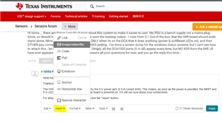
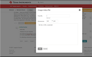
    For attaching a document, you need to click the "Insert" button as shown in the screenshot below. Navigate to "Image/video/file" and then add your word doc. 

    Let me know if you need any clarifications here.

    Regards,

    Ishita

  • Hi Ishita,  I'll describe TWO different scenarios: 1) the IWR by itself, 5v connected to its own psu socket.  In this example, NOTHING happens, no LEDs. 2) IWR attached to the DCA1000 via 40w cable.  Now, LEDS as you described light, and do so regardless of whether I apply 5V to the IWR connector on the one on the DCA - although the DCA SW3 is in a different position i.e the DCA gets it power from the PSU, or from the IWR.  In NONE of these cases, do I see any XDS ports in Windows, bit I DO get the DCA1000 ones.  The screen shot shows 1) BOTH DCA1000 USB's connected and J8 of theIWR1843_deviceScreenShots.docx IWR 2) DCA1000 FTDI USB plus J8 on the IWR, which seems to be what the training video requires.  No XDS in any configuration.

  • Hi,

    I was trying to think of a mechanism to explain the different behaviour i.e. IWR by itself, and on the DCA - perhaps the supplies & regulation is different?  However, just to re-re-check where I've been before, I re-measured my PSU output, with a different multimeter.  It was quite a bit less that 5V (I did check it before!). So - I now have the IWR powering up ok, AND I have XDS ports appearing in windows, and the drivers installing OK.  On wards to the Visualiser - but I can't get this past the serial port setup: it just says to download the CloudAgent, which I've done, and its visible & enabled in Chrome.  SO - I'm much further on (user error again!!), but would like some help with the visualiser - at least now things should be starting to happen as you expect them to!

  • Hi, I'm going to add two comments this time - related, but different, so I'll keep them separate. As for getting the device to power up etc - my last comment didn't seem to explain everything.  I've looked further, and in deed there's more to it. Certainly I seem to have a broken meter, and so my supply voltage was low - however, this didn't really explain what happened.  It now turns out that (even with good 5V), it really does matter how you power the modules. Given that there's a switch on the DCA which implies you can power things either way round, this is just not so.  I should point out that I chose first to power both modules via the DCA power connector, because the one on the IWR is very poor, giving intermittent contact, and you have to get the angle just right.  After more experiments, it seems that there are different results i.e. what LEDs light, but also whether things actually boot (now it looks like its working and I can see what the leds ought to to).  The ONLY way to get both IWR and DCA to boot AND to get the XDS ports to appear is to power BOTH modules.  Eventually you can see that between the user guide & vidoe it does say to do this, but perhaps it needs more emphasis that this is the ONLY set up which actually works - other ways round (using just IWR or DCA but not both power connectors) can look rather like its working, but it isn't.

  • Today's second observation: I may need to buy a separate PC for TI development, as this PC has been trashed twice now.  Today, windows actually crashed "unsafe activity" - I suspect this may be due to USB and ETHERNET ports on the IWR/DCA coming and going sporadically, due to the poor power connector on my IWR.  Also, when I went to do my regular shutdown & restart (seems to be good for windows to do this), it couldn't even find a bootable drive.  The most that I'd done previously was down-loading and installing all the various TI components the user guides etc say to do.  I have a recovery disc, so got it going again and let windows repair run - which eventually said it couldn't repair the disc.  I've seen this before - it is fixed, and boots OK this time.  As far as I've seen so far, all is still there, except the off-line version of the visualiser - presumably windows repair thought this was unsafe and removed it?  Just to let you know that installing the various TI components doesn't always go smoothly...

  • Hello Alan,

    Thankyou for your detailed explanation. I do want to clarify some things out.

    There are two ways to power the DCA1000 module. One is to have its own independent supply, other one is to get the Power from the mmwave sensor (and not the other way round). These are the ONLY two ways and both of these have been tested, validated and used across by the customers. 

    Now coming to your below statement, I want to clarify that You cannot supply power to the IWR module using the DCA1000.

    I should point out that I chose first to power both modules via the DCA power connector, because the one on the IWR is very poor, giving intermittent contac

    An independent power supply to the IWR board, should power up the board and you should see the corresponding LEDs glow. If not, then either your power supply needs to be checked, or there is some issue with the board. But as you confirmed that the board is powering up fine in your later replies, I suppose this problem is eliminated.

    Now coming to your other problem of installation of various TI tools, sometimes there are certain windows firewalls blocking the installation. Even for the DCA1000 to work, you would need to remove some firewalls for the proper functioning of the tools and the device. But none of the tools are harmful to your system. 

    On your mmWave Demo visualizer issue, I would request you to create another thread so that its assigned to our correct representative. 

    Let me know if you need any clarifications. 

    Regards,

    Ishita

  • Hi Ishita, the first problem (entirely due to me!) was too low a supply voltage, and seemingly the DCA is more tolerant, so more LEDs came on, making it confusing to understand what was going on.  I note your reply re IWR+DCA or DCA via the IWR as the only power configs - might be an idea to add that actual text to the docs etc.  On my IWR, there is a physical issue with the connector - its clearly a different design to the one on the DCA, which works every time, whereas the IWR one has to be in just the right place ... and can come & go rapidly if you touch anything & I assume this is why it crashed windows via the USB, but that is assuming!  As for getting the software going, I understand the need for a new thread.  However you may know one last point: I've also tried the mmWaveStudio - it sees the hardware and connects to FTDI OK.  Can you tell me which interface it means by the RS232 connection? Is it IWR J8, or the other one on the DCA, which appears in windows as a dual RS232.  Many thanks for your help so far - its always "interesting" getting going with something new, it can take a while until it trains the user!

  • Hello Alan,

    Yes, we totally understand and that's why we are always here to help you Slight smile. Please feel free to shoot any kind of questions you might have or any clarifications you need. 

    On your response, please find my comments below : 

    I note your reply re IWR+DCA or DCA via the IWR as the only power configs - might be an idea to add that actual text to the docs etc. 

    Yes, you are absolutely right. This is captured in the DCA1000 User's guide (section 3) : https://www.ti.com/lit/ug/spruij4a/spruij4a.pdf 

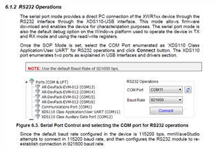
    Can you tell me which interface it means by the RS232 connection? Is it IWR J8, or the other one on the DCA, which appears in windows as a dual RS232. 

    This is on the IWR device. Please see a snippet from the mmWave_studio_user_guide.pdf below : 

    Hope this gets you started. 

    Regards,

    Ishita

  • Hi Ishita, well, much progress since last entry!  I'm all the way into mmWave Studio!  This brings me to an important tech question: the LDO regulator.  How do I know which way to set this for my particular board? The package says "1V mode".  Is that it wants 1V, or its being supplied?  Don't want to fry things having got this far.  The difference from earlier is just being very careful how to interpret what the docs & videos say...different terms seem to be used in different places, so it doesn't help the beginner get going.  Also, now I'm into the Studio and I've got the firmware on board - will the visualiser still work, or have I overwritten that code?

  • Hello Alan, 

    Please refer to the thread linked below for LDO bypass concerns : 

    https://e2e.ti.com/support/sensors-group/sensors/f/sensors-forum/957034/awr2243-if-use-internal-ldo-to-supply-1-3v-for-rf1-rf2-should-i-connect-pin-a13-a10-to-connect-vin_13rf1-2-external-or-only-add-filter-cap

    Also, I wanted to let you know that there would be no further activity on this thread as I'm out of office. 

    I would request you to create a new thread for any pending query by clicking on "Ask a related question" button so that its assigned to a relevant member in the team. 

    I apologize for the inconvenience caused and Thankyou for the cooperation. 

    Regards,

    Ishita 

  • Hi Ishita,

    OK - thanks for the help, I think I'm well on the way now ... but can't guarantee no further questions!