This thread has been locked.

If you have a related question, please click the "Ask a related question" button in the top right corner. The newly created question will be automatically linked to this question.

LMP91200: lmp91200

Part Number: LMP91200

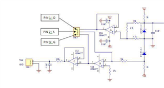
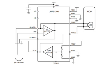
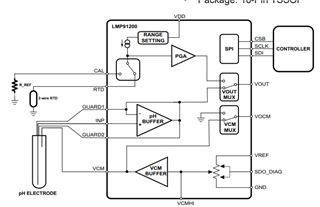
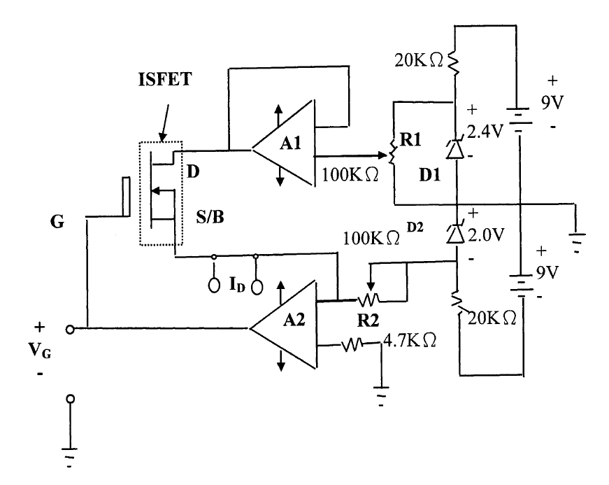
Dear Sirs, I want to use Your lmp91200 part to read isfet based ph sensor output voltage. I found out from Your datasheet and reference design it is foreseen for two electrode glass pH meters with guard. Isfet based ph meter is 3 electrode one composed of drain, source and gate electrodes. Usual circuit topology for isftet biasing and readback is based on two opa amps, one for biasing drain, one for biasing source and feedback output voltage to the gate so called cccv topology. I have doubts if I can connect my 3rd source electrode just to ground or guard inputs.

  • Dear Konrad - 

    Welcome to E2E and thanks for posting. It looks like the reference electrode for this type of sensor has the electrode itself in the solution and the other side to Vref, to keep it constantly biased. Do you have a datasheet for the sensor you are planning to use, which you could send the link for?  

  • Dear Josh, Thank You for Your fast answer. Datasheet of the isfet sensor I am going to connect to lmp91200 is here: http://www.winsense.co.th/item/item_image/winsense_isfet_ph_sensor_wips_datasheet.pdf

  • Dear Konrad - 

    Looks like you need this for the reference electrode. 

    http://www.winsense.co.th/item/item_3.html 

    based on the image, it would appear (from the wire colors) that indeed one wire might go to Vref, and the other to ground, with the reference in the solution. As their website is light on content, i would suggest you contact Winsense and ask them to give you more documentation on that combo. 

  • Dear Josh, when I am comparing their circuitry suggested for readback I can see following:

    Looking more carefully I can see 9V from battery limited with current with 2k to reference voltage diode of 1.235V, farther divided down to 0.3V for biasing VD. The currenct flow over Drain and source is converted to Voltage which keeps constant voltage on reference gate electrode. Ph Value looks like to be Vgate +/-200mV range. When looking to internal lmp91200 circuitry I can see biasing buffer so call vcm buffer, I can see buffer for ph readback which is voltage follower. I do not see so called current to voltage converter that could be used to apply voltage to gate electrode.

    In priciple when we could short source gate of isfet to ground that could have answer to the problem but it looks like we need this 3rd electrode to be connect to -1,235V potential +0.235V from Vd biasing which give around 1V at gate reference (inverting topology of opa amp B) +/-ph voltage. I do not understand how this is done inside lmp91200 IC itself.

    I also find out the some of datasheets showing lmp91200 with rtd and spi interface but the official datasheet presented at ti web page does not have the rtd and spi pins. Are there two types of the IC available or one of the previous versions had those pins and then the pins have been removed?

  • Dear Konrad - 

    In this case, with that sensor, it seems reference will drive the gate and the potential is measured from source to drain. I don't have any experience with this type of sensor topology. We do have reference hardware on the LMP91200 you can use to experiment with this sensor. It would be interesting to know about.

    With regards to the RTD and SPI connections, they were not removed internally, but we cannot support was previously specified for performance inside the IC, so before my time, the decision was made to just remove the features from the datasheet and are both individually noted in section 4 of the datasheet. (which is the revision history)