This thread has been locked.

If you have a related question, please click the "Ask a related question" button in the top right corner. The newly created question will be automatically linked to this question.

DRV5011: Cannot get placement correct to get the expected quadrature output with a 6 pole radial magnet.

Part Number: DRV5011

Hi,

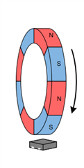
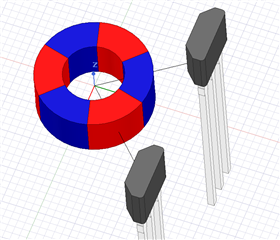
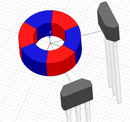
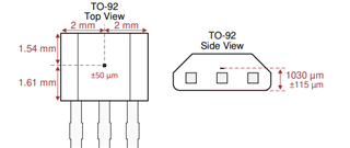
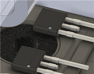
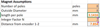
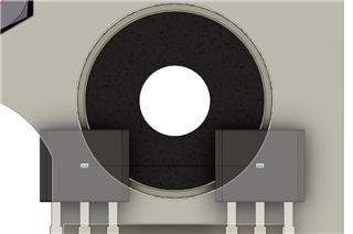
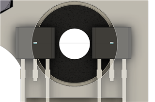
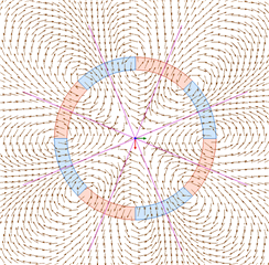
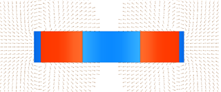
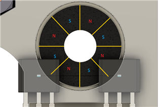
We are using a 6 pole magnet and we are using 2 DRV5011's below it. I created a drawing to simulate the design shown below. The drawing shows a 6 pole magnet with the poles 60 degrees apart and then a surface below the magnet that is 2.6mm( This is where the sensor will rest). There is an off set of 1mm which is the height of the sensor inside of the through hole package.

I am able to calculate a sensor to sensor distance of ~11mm. This is if we project the pole to where we expect the sensor to be.

When placed like this and tested, it does not give a quadrature output.

1. Is there something wrong with the logic in the design? 

2. Do both magnets need to be symmetrical about the center of the magnet?

  • Ajay,

    It's a little unclear to me how the sensors are oriented relative to the magnet and which package variant (SOT-23 or TO-92) is in use.  If the case is that the sensors are both installed such that the sensing element is parallel to the horizontal line at the bottom of your drawing, then each would observe a portion of the radial component and a portion of the tangential component of the magnetic field vectors, since the Hall element is sensitive to the portion of the vector which is normal to the surface of the package.  The result would likely produce a phase shift to the expect 90 degree separation you would be expecting.  Can you confirm the orientation of your devices?

    Scott

  • Hi Scott,

    The sensors are the TO-92 and the sensing face is facing up. The first image is the best way that I can describe how the sensor is oriented.

  • Ajay,

    Thanks for confirming. If the configuration looks like this:

    Then I would anticipate some phase error.  This is due to the sensor being sensitive to the component of the vector which is orthogonal to the face of the device.  However, this magnet is polarized radially, so each sensor will detect a portion of the radial and tangential components.  Relative to the magnet, one sensor is rotated 45 degrees to the left and the other is rotated 45 degrees to the right.

    The correct orientation for quadrature detection should look like this:

    It is also worth noting that the target location should be the physical location of the Hall element inside the package.  

    In the first case, with the wrong orientation, if the face of the device was used as a target, it would have resulted with the sensors being somewhat offset from 90 degree separation. In the second image, however, what is more critical is that the two devices are equidistant from the magnet, which you have already accounted for in your design.

  • Thanks for the information i think this makes a lot of sense. Ill see if this changes the signal at all.

    Thank you

  • Hi Scott, I decided to change the orientation of the encoder and magnet. I was wondering if the following orientations would work fine with the calulations I did. I prefer to use orientation 1 but I am not sure if this would work.

    Orientation 1


    Orientation 2

    Calculation

  • Ajay,

    These sensor packages will be sensitive to the component of the field directed in the z direction.  While there is likely some vector in this direction using a radial magnet, it is hard to tell how much just by looking. If the pole is face oriented(z-direction) then there should be a strong field component here.  If you've got the magnet and sensor handy, I would recommend running a test to verify you pick up enough field to get the output transitions you are looking for in this orientation.

    In both cases, The 3D images can make it hard to tell exactly where the sensor is relative to the magnet poles, but the spacing should be (n+1/2) poles away.  For example, if one sensor is perfectly aligned to the center of a North region, then the other sensor will lie at a boundary between North and South.

    With the sensors in this orientation, the rotation in X and Y should be of less concern.  As long as the sensor is aligned parallel to the face of the magnet, the Z component should be the same regardless of the rotation in the XY plane. This means that as long as there is sufficient field, that either orientation can work, and if the sensor location is aligned at the proper spacing (n+1/2) then you should get a quadrature signal.

    Thanks,

    Scott

  • Thank you for the information, I had an additional question regarding the placement. Does the location of the sensing element with respect to the XY plane matter. For example does the sensing element need to be coincident to the outside edge of the radial magnet or can it be closer to the center of the magnet, or does none of that matter as long as both sensors are equal distance apart from the center of the magnet with (n+1/2) separation.

    From my understanding because of the nature of z component of the magnet the sensor just needs to be equal distance apart from the middle of the magnet with (n+1/2) separation(i.e. both images below would work) but id like to confirm my understanding is correct.

  • Ajay,

    With the (n+1/2) spacing, if both sensors are radially equidistant from the center, then they should experience the same z component of the magnet with a 90 degree phase shift.  However, the key thing to remember is that the field from the magnet in the z direction needs to be strong enough to trigger the sensor.  With a multipole ring magnet, this gets a little tricky to visualize.  Consider these vector plots:

    Based on the drawings you have shown, it appears you have placed each sensor such that they would be perfectly in phase with each other in the second image.  Here, at 180 degrees apart, they would simultaneously experience the same pole as an 8 pole magnet spins.  

    The first image looks like it might be correct.  My sketch is a little crude, but it appears that if the boundaries were rotated such that the sensor on the left were aligned to a S/N transition, that the sensor on the right would be close to the N pole.  If that is the case, I would try to verify the sensors are able to detect the magnet properly on a lab setup based on the ranges you are working with in this design.

    The placement seems like you should experience an alternating Z component using the first example with the sensor location just outside the outer radius of the magnet.  In the second case, I would expect there to still be some Z component, but if moved much further inward the field starts to become parallel to the magnet face.

    Thanks,

    Scott