


Hi TI members,
I currently try to configure ''sample point'' between 75~87.5%.
However, when I try to configure sample point as 70% (parameter shown as fig.1), the actual sample point measured by instrument is 62.5% (fig.2). The "dcanBitTimeParams" comes out from API "DCANAppCalcBitTimeParams" is shown as fig.3.
My second try is to configure sample point as 85% (parameter shown as fig.4), the actual sample point measured by instrument is 75% (fig.5). The "dcanBitTimeParams" comes out from API "DCANAppCalcBitTimeParams" is shown as fig.6.
What is the formula for sample point, isn't it ((1+timeSegment1+timeSegment2)/(1+timeSegment1))*100%?
How can I configure sample point I want, for example, 80%.
Thanks!
Sincerely,
EricHuang

fig.1

fig.2

fig.3
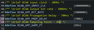
fig.4

fig.5

fig.6


