This thread has been locked.

If you have a related question, please click the "Ask a related question" button in the top right corner. The newly created question will be automatically linked to this question.

TUSS4470: Cleaning up my waveform

Part Number: TUSS4470

Dear TI,

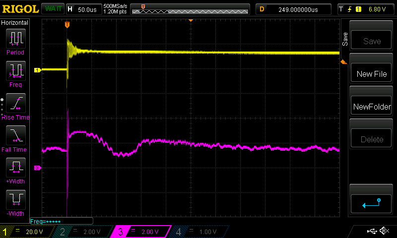
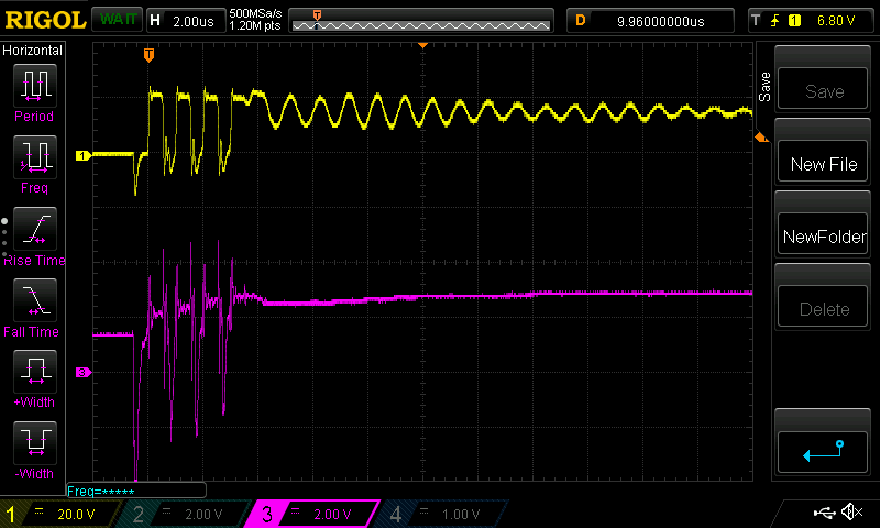
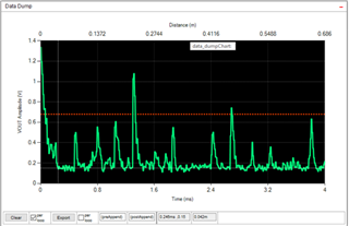
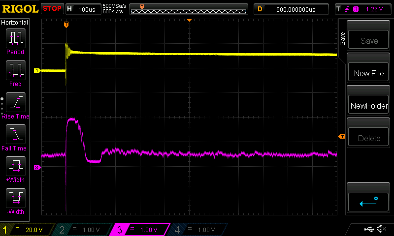
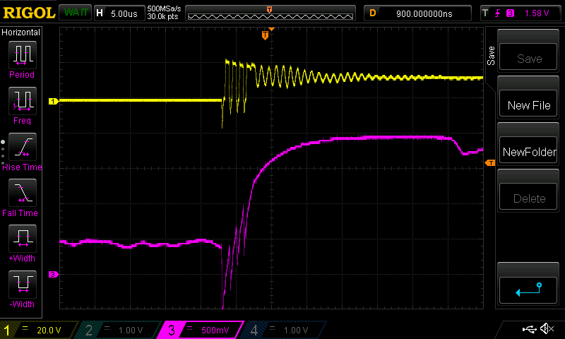
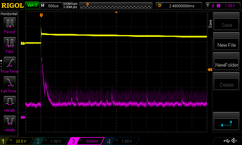
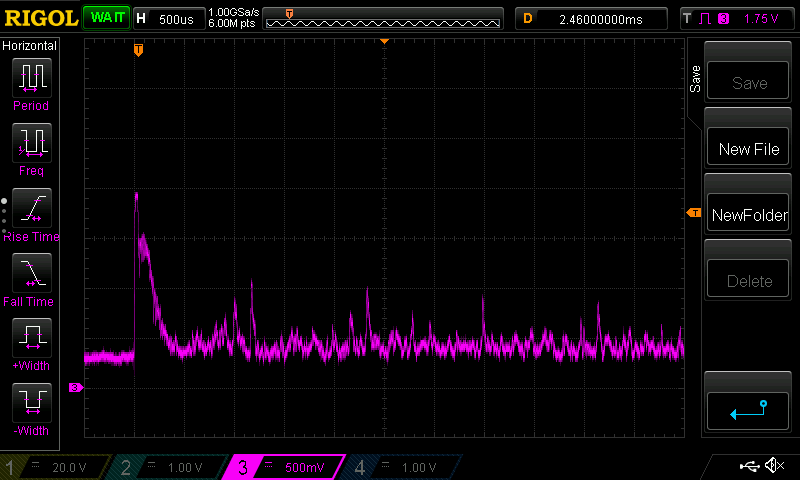
I've got a TUSS4470 on our custom board and connected to a PZT and we're trying to measure fluid level. The container this is attached to currently is metallic. I was wondering if you could take a look at my waveform to see if you can think of an approach to clean up or get a cleaner signal out. I can see 2 bumps which could be used to calculate the fluid level in this case but I'd like to see nice spike echo responses.

Here is my configuration setup:

Add Value
0x10 0x5F
0x11 0x00
0x12 0x1C
0x13 0x02
0x14 0x00
0x16 0x5F
0x17 0x13
0x18 0x54
0x1A 0x04
0x1B 0x02


  • Just another note, with the dev kit and using the GUI we we're seeing something more like this which is what we need to achieve with our custom board.

  • Hello Louis,

    Thank you for your question, I agree that the receive signal on the custom board should possess a more prominent spike for the return signal. Did any configuration settings change when switching from the EVM to the custom board?

    Additionally, are the physical testing setups the same between the custom board and TUSS4470 EVM? I ask, because the scale on the first scope shot with the custom board is set to 50us /div, and the EVM GUI has spikes in the ms range. Did you by chance see any return signals that lie outside the horizontal range of the scope? Understanding the tested range between transducer and target can help me to know the expected time of flight for the application.

    Finally, I am happy to look at schematic and layout of the custom board if you suspect the problem lies there.


    Thank you,

    Jacob

  • Hi Jacob,

    Thanks for getting back to me. 

    The setup has changed. Physically the container has changed but is very similar. In firmware the configuration bits in the TUSS4470 are all the same except that the LNA_GAIN is set to 20V/V from 10V/V because I found the signal was better. I haven't yet trialled adding hot glue to the sensor which I'm doing now. On the scope scale yes you're right but after around a 500uS there was just no signal and based on the fluid level I'm expecting a response flight time of 215uS which should fit in twice (with a little time for the first PZT peak).

    It would be fantastic if you could review the schematic and layout. How do I go about sending you files?

    Thank you,

    Louis

  • Hi Louis,

    Thanks for describing the application. The mounting of the transducer can certainly affect the performance of the sensing system. I will be interested to see if the hot glue improves the receive signal any.

    If you accept my friend request through E2E, I will be able to private message you my contact information. That is likely the easiest method for reviewing the files.

    Let me know if you have any questions.

    Regards,

    Jacob

  • Hi Jacob,

    The transducer is wired from the board to the container using wires that are around 300mm in length during development. This is similar to the previous testing. However this is much more than the end solution which will be around 35mm. 

    Adding the hot glue made the signal worse. I now can't see any second peak.

    Something also useful to note, originally I was scoping both the PZT line and the TUSS4470 Vout line. See image below (this now has glue so will be slightly different to the first image post).

    However, when I remove the scope from the PZT line the signal changes quite a bit. As the scope probes will be changing the impedance on the PZT line, should this make me think that impedance on the PZT connections is something to investigate? See image below without scope probe on PZT line.

    I'll attach another PZT to the container without the glue and check the TUSS4470 Vout signal without the glue. Have you seen situations where adding the glue made the signal worse?

    Another question, does anything to do with the dev kit manipulate the data in anyway or is the VOUT signal shown in the TI GUI the raw ADC data (obviously converted to volts)?

    Thank you,

    Louis

  • I have seen scope probes negatively affect the PZT due to the capacitance of the probe, but it is rare to see the transducer performance degrade due to the hot glue being added. Typically, the glue provides mechanical damping for the back side of the transducer, improving the ultrasonic system. I am including an app note that covers more in terms of transducer mounting (Link here), but I am surprised to see the results looking worse with the addition of the hot glue. Was the transducer mounted to the metallic container the same way between the setups? I just want to verify that the method for adhering the transducer hasn’t influenced the ultrasonic sensing performance.


    For the dev kit, the Vout signal in the GUI is representative of the raw data. The demodulated analog signal is processed by the ADC on the MSP430.

    As one last method for ensuring test conditions are identical, is it possible to connect the dev kit EVM to the setup you are currently using (~215us TOF setup)? If you could probe the Vout signal similar to how you did in figure 3, it would isolate the difference in performance to be either setup related, or board related. It may seem redundant but it would give us a very high confidence level as for where to look next. 


    Please let me know if you have any questions.


    Thank you,

    Jacob

  • Hi Jacob,

    Re the setups, all good points, I've ordered another dev kit to try out in place of my custom board (our previous dev kit stopped communicating over SPI for an unknown reason). I should hopefully receive that today and will be able to get back to you on this. I don't think it's redundant at all, it'll rule out the setup which will prove it's to do with our custom board.

    All of the previous waveforms (TI GIU and scope) have been on a metallic container. On a plastic container with my custom board I'm getting fairly good echo signals back. See image below:

    Thank you, Louis

  • Hey Louis,

    Great to hear you are receiving strong return echo signals in the plastic container. I am interested in understanding why the metallic tank differs in performance.

    As previously mentioned, the mounting method can have significant influence in performance. We typically recommend using CYA glue between the transducer and tank wall to adhere the PZT. This glue offers enough flexibility to be suitable for PZT applications.

    Additionally, it is very important to have a homogeneous medium for the sound waves to pass through. Any form of air gap in the material, or mounting, will significantly reduce the strength of the intended echo.

    Ultimately, I see this as a great step forward. It is great to see the custom board working as intended. Typically, the medium being plastic or metal should have little influence on the strength of the ultrasonic waves.

    I will be interested to see if there is any performance difference between the dev kit and the custom board with an identical setup.

    Please let me now if you have any questions.

    Regards,

    Jacob

  • Hi Jacob,

    I've setup the dev kit on my setup here and I'm getting fairly good results.

    The signal responses aren't as big as the plastic container but still probably big enough to pickup. I did use the same technique when attaching the PZT to both the plastic and metal container so unless the stainless steel container reacts with the adhesive I'm sure sure about this. We might need to double check the method we're using. The steel container has a solid wall so shouldn't dampen the signals much.

    Thanks for your response, Louis

  • Hi Louis,

    Thanks for replicating the test using the EVM, it is great to be able to directly compare the two results in an identical configuration. The dev kit results look usable for TOF measurement. I agree that the solid metal shouldn’t dampen the transducer oscillation much.

    Additionally, I wonder if you can push the HPF Fc to a higher frequency to possibly improve the SNR of the system. 0x1F represents 218kHz, but this value can be pushed all the way up to 500kHz with 0x2F

    Finally, PSRR can have significant influence on the device. The VDD pin drives the analog reference for the device. Any noise on this line can affect the performance of the system (section 9 of the datasheet).


    Please let me know if you have any questions.

    Thank you,

    Jacob

  • Hi Jacob,

    I've currently got my filter configured to be HPF at 400kHz with the register BPF_CONFIG_1 set to 0x1F and BPF_CONFIG_2 set to 0x00.

    I've tried using the HPF with:

    • BPF_HPF_FREQ  = 0x20 (minimum)
    • BPF_HPF_FREQ  = 0x1F (maximum) and current setup is best.

    I also tried using the BPF with:

    • BPF_HPF_FREQ  = 0x00 (minimum)
    • BPF_HPF_FREQ  = 0x2F (maximum)
    • BPF_HPF_FREQ  = 0x2F + BPF_FC_TRIM = 0x07 and setting BPF_FC_TRIM_FRC (maximum extended) and current setup is best.

    So I think our filter setting is OK.

    Regarding the PSU circuitry we have a battery to LDO to MOSFET PSU switch to TUSS4470 so it should be fairly noise free. I just scoped the line it's pretty clean although it was difficult to scope so I'll not rule it out.

    Next I'll try to drive the dev kit from my hardware.

    Thank you,

    Louis

  • Hi Louis,

    Thanks for trying the filter changes for the HPF and BPF option. I am happy to know the current settings used are the best suited values for the application.

    I agree that the VDD analog voltage reference will be pretty clean given the setup. Just one more item crossed of the list of potential electrical culprits.

    The test data for driving the dev kit with the custom hardware will provide a great idea of where to continue debugging.

    I appreciate your patience, and all the test data you have been able to provide. I will continue to discuss with the team regarding the correlation of data, and where the difference in performance may be.

    Thank you,

    Jacob

  • Hi Jacob,

    After you and your team kindly reviewed our schematics and layout and identified a grounding issue on CFLT and CINN, we've since modded our custom board to get around this and also made sure we removed the scope probe from the transducer. As you can see below, the signal has improved lots. 

    I think this should be good enough for me to programmatically determine the TOF which is great!

    Thank you so much!

  • Hi Louis,

    Thanks for testing the ground changes for CFLT and CINN.

    It is great to see the drastic improvement in quality of the Vout signal. I expect this to be a detectable return echo for TOF measurements.


    Please let me know if you require any additional assistance with the project. I am always happy to help!

    Regards,

    Jacob