This thread has been locked.

If you have a related question, please click the "Ask a related question" button in the top right corner. The newly created question will be automatically linked to this question.

LDC1614EVM: what is most up to date firmware?

Part Number: LDC1614EVM
Other Parts Discussed in Thread: LDC1614,

Hi all,

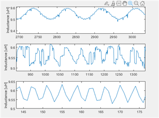
Recently I have been having some issues with the LDC1614EVM. As this is a different question than I previously posted, I wanted to make a new thread. After updating the firmware on my LDC1614EVM (SV601126 C) to the one found in C:\ti\Sensing Solutions EVM GUI-1.10.0\EVM Firmware\LDC1614_RevB, the results I got from my measurements were not making sense. I also noticed some changes in the EVM gui when starting it up. The Fref divider code was suddenly set to 3 (initially 1) and the reference counter was 1024 instead of 65535. The D2 LED near the MSP uC was green. 

After that I flashed the firmware found in C:\ti\Sensing Solutions EVM GUI-1.10.0\EVM Firmware\Older Revs\FDC2x14_LDC13xxRevB_LDC16xxRevB_EVM_Firmware.txt, the D3 LED near the MSP turned red. However, the settings were back to what I expected in the GUI, being Fref divider of 1 and reference counter of 65535. Also, the measurement results returned to what I saw before trying to flash the device at all. 

I'm kinda clueless on what contents in the firmware dictate what measurements I get. I suspect that the latter firmware version I have put on the EVM now is correct, but the red D2 LED makes me wonder. 

So my question is, what is the firmware version that should be on the LDC1614EVM (SV601126 C)? As it seems that measurement results are influenced by different versions.

Thanks for the hep in advance.


Kind regards,

Jim

  • Hello Jim, 

    The C:\ti\Sensing Solutions EVM GUI-1.10.0\EVM Firmware\LDC1614_RevB firmware is the latest version. The difference in the measurements is likely just a configuration change between the two firmware files, especially if looking at raw code. If you are using the newer firmware, you can always change the configuration to match the previous settings but the default will be different. 

    Best Regards, 

    Justin Beigel

  • Hi Justin,

    Thanks for the response. The results I'm getting are very different depending on firmware version. In the figure below, the top one is the older firmware version and the second is the up to date one. Both were with the same configurations settings: single channel 0, internal oscillator, settle count 1024 and ref count 1024.The standard coil coming with the EVM was used. In the data streaming tab, the EVM output rate was used. This also seems to impact the data written to the .csv file, as the top and bottom figure had the same configuration settings, but the EVM output rate was used for the top one and the 50ms update rate for the bottom. 

    Do you have a suggestion how I can check if the data given by the LDC1614 is same for both firmware version? The top figure is in line with my expectations, but I cannot imagine that the sensor measures something different based on the firmware. Perhaps I should not use the MSP uC to readout the data, but use an Arduino or something like that. 

    With kind regards,

    Jim

  • Hello Jim, 

    Reading the data with an Arduino is a possible solution. This would require setup on your end but if you create an initialization portion to the Arduino code, then you can completely ignore the MSP firmware. 

    I see that the units are in uH on the graphs, can you also compare the raw data codes from the device to better see if there is a difference in the data. This would remove the calculations that the GUI does. Also, it looks like there is some target movement in the data, if you were to take some samples without a target at all, does the data look the same? 

    Best Regards, 

    Justin Beigel

  • Hi Justin,

    The data in the .csv file is sampled at the same rate for both uH and raw data, so there is no difference between the two. I expect that this has something to do with you the data is written into the .csv file.

    In the figure below you can see that there is a difference between the two firmware versions wrt logging the data. The target is not moving, so the orange data set is what I would expect. With the most recent version, I notice two things. The data logged in the  figure below is more jumpy, while there should be no reason for that. Another thing is that in the data streaming GUI the data is a lot more sluggish and totally not fluent wrt the older firmware version.

    As I will not be able to figure out why this is the case, I am going to see how I can connect an Arduino (or perhaps a Raspberry Pi) for further prototyping. Thanks for the answers thus far!

    With kind regards,

    Jim

  • Hello Jim, 

    I have also confirmed the delay in the data streaming GUI on my end but haven't found the cause for it yet. When connecting a Pi or Arduino, the I2C pullups are on the MSP portion of the board so if that is snapped off, you will have to make sure the pullups are handled by your external controller.

    The timing of reading the data is covered in the datasheet, but there is also more information available in the LDC1312, LDC1314, LDC1612, LDC1614 Sensor Status Monitoring app note. 

    Best Regards, 

    Justin Beigel

  • Hi Justin,

    Thanks for confirming. Perhaps something can be done to resolve it by TI? 

    For the particulars using an Arduino (or something else), I'm familiarizing myself on how to approach this. The datasheet is not totally transparent on how the timings are generated and how the RCOUNT relates to the output resolution. The range of conversion times is from 1.2us to 26.2ms, but it is not mentioned that this is calculated with an external oscillator of 40Mhz. Also the equation to do this is different in SNOA944, where the +4 term is not in the equation. Not that it will matter that much for the final application.

    Do you perhaps have some nice libraries (to use I2C and the LDC1614) present to use if I were to use a dev board that needs C/C++ code? For Arduino I was able to find a nice library that provides this.

    Thanks for your help!

    Kind regards,

    Jim

  • Hello Jim, 

    I am looking into the firmware for why it cases the delay and offset. As for the timing using an external controller, it is best to look for the DRDY signal and use that to start a read of the data. If you are taking data at a slower rate than the device is sampling, you can either omit the intermediate data points or try to duty cycle the device by putting it to sleep between measurements. There are benefits to both but if you are omitting intermediate data, the DRDY flag may will likely always appear when you go to read a measurement. The proper formula for the RCOUNT is without the +4, the datasheet has the correct equation with RCOUNT in the register map section as well. 

    For libraries, we have the firmware for the EVM available online (MSP430 Firmware Source Code for Multichannel LDC) and it includes .h and .c files (in the library folder) you can use as a reference for C/C++ code. 

    Let me know if you have any other questions. 

    Best Regards, 

    Justin Beigel