This thread has been locked.

If you have a related question, please click the "Ask a related question" button in the top right corner. The newly created question will be automatically linked to this question.

FDC2212: IDRIVE register does not change the Vpp of the LC tanks.

Part Number: FDC2212
Other Parts Discussed in Thread: FDC2112

I am working on two pcb's, one of them with FDC2112 and one with FDC2212. 

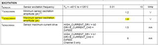
I have the same problem in both. I cannot change the Vpp of the channels using the IDRIVE registers. 

I will attach photos of the schematic and pcb and the register settings that i am using.

The setting are:

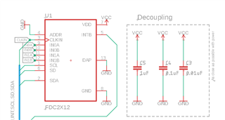
Single channel operation, external 40MHz crystal, HIGH_CURRENT_DRV -> Disabled, SENSOR_ACTIVATE_SEL -> use idrive.

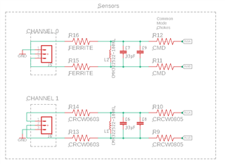
Channel 0 works in differential configuration with two plates (12.5cm x 10cm) attached to IN0A and IN0B respectively.

channel config:

RCOUNT 0x200
OFFSET 0x00

SETTLE COUNT

0x1E
IDRIVE  - 
FIN_SEL 0b10
FREF_DIV 2

Config:

AUTOSCAN 0
RR_SEQUENCE 0
ACTIVE_CHANNEL 0
OUTPUT_GAIN 0
DEGLITCH 0b101
SENSOR_ACT_SEL 0b1
CLK_SRC 0b1
CURRENT_DRV 0
FREF 20000

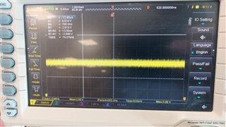
The board is powered through an esp32 voltage regulator which is a bit noisy. The power supply on the FDC2x12 power pin is at 3.3V with ~= 350mV noise.

I would appreciate if someone could help me troubleshoot this issue!

  • The oscillation's Vpp is around 1.80 - 2.00 Volts regardless of IDRIVE set and if i touch either sensor plate it goes to 2.10 Volts and stays there.

  • Vasileios,

    Thank you for your post and your interest in TI products.

    According to the data sheet, you may be seeing the max output voltage.

    In section 8.5, the typical value for the max sensor oscillation amplitude is 1.8 Volts peak.

    Regards,
    John

  • Hello John and thank you for your help. 

    I am getting values in the range of 1.8Vpp to 2.2Vpp in both chips.

    Shouldn't this value be lower, and change by changing the IDRIVE register?

    I already read the datasheet many times and still cannot understand if this is a hardware or software issue.

    Best Regards,

    Vasileios

  • Vasileios,

    You mentioned your FREF is 20kHz, and it looks like your FSENSOR is 4.2Mhz. Should FREF be 20MHz?
    That would meet the requirement of FREF > 4*FSENSOR. 

    Also, can I propose some experiments to see if you can get the CH0 behavior you are looking for?
    First, please remove or short out the common-mode chokes.
     I am skeptical they are the problem, but they can be added back later.

    Next, set SENSOR_ACTIVATE_SEL to b1, and HIGH_CURRENT_DRV to b0.
    Next, try different values of CH0_IDRIVE to see if you can get the sensor voltage somewhere between 1.2V to 1.8V.

    Apologies if I am asking you to retrace some steps.
    Some of the filed/register names in your post don't exactly align with those in the data sheet and I want to minimize the risk of mis-communication.

    Please let me know what results you see.

    Regards,
    John

  • John, sorry for not naming the registers correctly. 

    FREF is 20MHz this was my mistake when i posted the question. (This is not in the chip though, it is used in the code for the calculations.)

    I have tried exactly what you suggested already with no luck.

    At first the board was soldered without the Ferrites and Chokes, with 0 Ohm resistors. Then i firstly added the ferrites and then the chokes hoping it would resolve the issue. 

    SENSOR_ACTIVATE_SEL is set to b1.

    HIGH_CURRENT_DRV is set to b0.

    Is it possible that i am setting the frequency divider wrong? As i understand from the datasheet, FREF is set by setting the CH0_FREF_DIVIDER register to 2.

    Since the external clock is 40MHz this should result in an FREF0 of 20MHz which meets FREF > 4*FSENSOR.

    I did not set CH0_FREF_DIVIDER to 1 because this would violate FREFx =< 35 MHz  from Table 1 -> Single-channel operation.


  • Vasileios,

    It sounds like you're doing everything right, but a problem persists.
    At this point, I can only suggest some things you have probably done already.

    I will try to reproduce your results on one of our EVMs, and will update this thread by COB on Thursday.

    Regards,
    John

  • Vasileios,

    I have experimented with device settings using one of our EVMs and GUI, but have no helpful results to report yet.
    I will continue experiments, and will update this thread no later than Tuesday.

    Regards,
    John

  • Vasileios,

    Apologies for the delayed reply.
    I have been unable to reproduce what you have seen using an EVM and our GUI software. 
    Are you still seeing the problem? 
    If so, what are your thoughts on the next steps we can take?

    Regards,
    John

  • John, 

    Thanks a lot for your help. The problem persists.
    The circuit around the chip was designed in accordance with the EVM schematics so the only thing that comes to mind is that the chip's supply which is noisy, somehow affects the output current on the channels. The chip is supplied by the 3.3 pin on an Adafruit huzzah32 which contains a voltage regulator. I am attaching a snapshot of the oscilloscope from GND to FDC's V pin.

    • Vmax = 3.58 V
    • Vmin = 3.06 V
    • Vpp = 520 mV

    Do you think this could cause the problem? If so i could try a more steady supply in the next board revision.

    Best Regards,

    Vasileios

  • Vasileios,
    Before waiting on a board rev, would it be possible to try a hack of the existing board?
    Can you cut the PCB VCC runner to the FDC2212 and supply the device with an external bench power supply?
    If that is possible, it might help settle the issue.

    If the hack isn't possible - or doesn't work - can you share your schematic and layouts?
    We can review them on our end and provide feedback.

    Regards,
    John

  • Hello John, the noise on the power supply was coming from the lipo battery. 

    I run both the pcb and huzzah32 controller from a bench power supply @ 3.3V and verified noise <50mVpp on the Vpp of FDC2212.

    The problem persists. I cannot publicly share schematics and layout but I will ask for permission to send them in a personal message if this is acceptable from your side.  

    Thanks again for the time you spent on this issue.

    Best Regards,

    Vasileios