This thread has been locked.

If you have a related question, please click the "Ask a related question" button in the top right corner. The newly created question will be automatically linked to this question.

FDC1004: parallel plate capacitor at short distance

Part Number: FDC1004

Hello everyone,

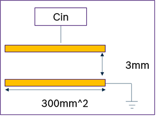
I want to detect the distance with a parallel plate capacitor. Is it possible to measure a distance of 3mm with an electrode area of 300mm^2 with the FDC1004EVM?

Is it possible to estimate the amount of disturbances such as noise etc. at this distance?

Or how accurately can the distance be measured at this distance if it has been calibrated for the distance?

Regards,

Maxi

  • And another question. How far should be the distance between my electrode for sensing the distance and the electrode for my active shield? The document says it should be as close as possible to protect form interference and parasitics. But with a minimal distance between the electrode for sensing and shielding my sensitivity decrease. Is the interference so great that the minimum distance between the electrode for sensing and shielding is required?

  • Maxi,

    Thank you for your post and your interest in TI products.

    Based on some idealized calculations - and assuming only air is between the electrodes - it looks like the nominal sensor capacitance will be about 0.9pF, which is within the FDC1004's ability to measure. Just so you know, the strength of these devices is being able to detect a change in capacitance as opposed to the absolute capacitance, like you might measure with an LCR meter. 

    The change in capacitance per change in distance (ΔC/Δd at a nominal 3mm distance) is about -295 pF/meter. If you divide the measurement resolution ( = 0.5fF from the front page of the data sheet) by this -295 pF/meter, you get a minimum detectable change in distance between the sensors of 1.8um. This calculation is kind of idealized, so design margins should consider a larger number than the 0.5fF, as well as the reported absolute error of  ±6fF. 

    The impact of noise, etc. will be highly dependent on the external noise, which the shield should be able to help with. We don't have any ready calculations, other than the output noise reported in the data sheet (= 33.2/aF/sqrt(Hz)).

    The general advice for the shield placement is to put it as closely as possible to the active sensor. The goal is to drive the shield with a waveform that is identical to the sensor's waveform. For that to be most effective, the signal paths for the two waveforms should be as close to identical as possible. Imbalances between the sensor signal and the shield signal can cause decreases in the effectiveness of the shield and the sensitivity of the system.

    Regards,
    John