This thread has been locked.

If you have a related question, please click the "Ask a related question" button in the top right corner. The newly created question will be automatically linked to this question.

AWR2243: Issue with receive signal on Imaging Radar

Part Number: AWR2243
Other Parts Discussed in Thread: MMWCAS-RF-EVM, TDA2

Hello,

We have designed an Imaging Radar Platform based on AWR2243. Data is transferred over LVDS from the chips. CRC calculated on the chip and on the final destination are matched, so we are confident that the data from ADC is received correctly.

We are testing now various configurations but have a issue with sampled received signal.

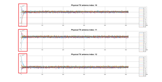
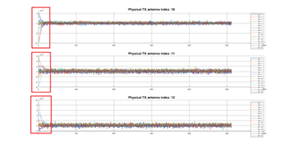
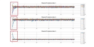
We are using TDM mode with 12 Tx and 16Rx. The issue we are facing is next:

  • If master chip is transmitting, no matter Tx1, Tx2 or Tx3, the received signal from his Rx antenna is having strange behavior in first around 10 samples. The other 12 Rx from slave chips have values as expected
  • When any of the slave chips is transmitting, again no matter which antenna, only the receive antennas from the chip that is receiving are corrupted in the same manner as above
  • It is always only one Tx antenna on, but the same problem on receive antennas is seen only on the chip that is transmitting
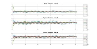
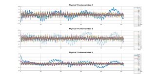
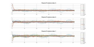
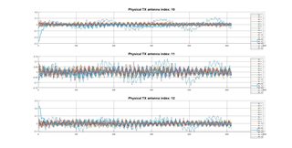
  • On above pictures Tx antenna index 1 represents first transmit antenna of master chip and antenna index 12 third antenna of fourth chip
  • On above pictures Rx antenna index 1 represents first receive antenna of master chip and antenna index 16 fourth antenna of fourth chip
  • Chips are positioned same as on mmWCAS-RF-EVM.

We suspected a problem with power supply but looking at oscilloscope all 3V3, 1V8, 1V2 and 1V0 look inside tolerance.

Changing ADC start time, TX start time, Fs, slope or TX backoff provides no improvements.

Do you have any advice how to proceed?

  • Hi,

                Can you please elaborate a bit more on your raw data capture mechanism? Are you using the TDA2 EVM for data capture(TDA2 uses CSI2 to capture data)? 

  • We have our own design of front end board with 4x AWR2243 and custom DSP board. We are sending the data over LVDS (900Mbps) from all 16 channels to custom DSP board which is sending the data to PC. We are currently testing TDM mode with 12 chirps in loop, every transmit antenna having one chirp in loop. All 16 receive antennas are always on.

    We calculate CRC on PC and it is match to the one calculate by chips, so all the data are received correctly.

    The issue is seen only on first 10-15 samples on receive channels of the chip that is actually transmitting.

  • Thanks Darko. Can you please also share details about the profile config?

  • Hi Abhed,

    Profile config, index 0:

    Start freq: 77GHz

    VCO Select: 0x02 (77-81 GHz)

    Idle time: 7.5us (15us also tested with same behavior)

    ADC start time: 4us (15us also tested with same behavior)

    Ramp end time: 73.7us (93.7us also tested with same behavior)

    TX start time: 0us (10us also tested with same behavior)

    TX output backoff: 0

    TX phase shifter: 0

    Freq. slope: 47.7 MHz/us (27.7MHz/us also tested with same behavior)

    ADC samples: 512 (256 also tested with same behavior)

    ADC Fs: 7400 ksps (3700ksps also tested with same behavior)

    HPF corner frequencies: both 0

    Rx Gain 30.

    Configuration is the same for all the chips. 12 transmits in a loop, 42 loops in a frame.

    We have connected your mmWCAS-RF-EVM with our DSP system, send the same configuration (working in LVDS mode, not CSI2) and we do not see the issue.


  • Thanks for the details. Can you please confirm if you varied the mentioned parameters

    Idle time, ADC start time, Ramp end time, TX start time, Freq. slope, ADC samples, ADC Fs..................all together or one by one?

  • Hi Abhed,

    One by one where it was possible.

    For example when I decreased the Fs I tried both to decrease number of samples and decreasing the slope (also extending ramp end time) to be inside 3.8 GHz BW.

    I suspected power supply (when chip is transmitting the power consumption is higher) but all of them look stable (some 30mV dropout when transmitting but inside the limits).

    I suspected also synchronization, but since the anomaly is moving from chip to chip only when the one is transmitting (but OK when other are transmitting) I'm not sure if it is that.

    Any help from your side would be very helpful.

    Regards

  • Thanks. I would advice at first to only increase the ADC start time and check. 

  • Hi Abhed,

    I have increased ADC start time up to 20us with no improvement. Of course, I could not do that without changing other data, like decreasing number of samples.

    We are collecting 512 samples at 7.4Msps which lasts ~69.2us plus 4us for ADC start time we are the limit of ramp end time which is 73.7us.

    Also, we have seen one more issue stated on this question:

    https://e2e.ti.com/support/sensors-group/sensors/f/sensors-forum/1038195/awr2243-adc-value-issue

    Does this help you to know in which area we should look for the issue?

    Best regards,

  • Ok. Can you also increase the HPF cutoff freq and confirm?

    Regards

    Abhed

  • Hi Abhed,

    We increased both HPF1 and HPF2 to max value.

    It provided improvement, but I see it as just bypassing the issue.

    Do you have advice where to look for the issue? Synchronization, power supply, layout...

    Regards,

  • Hi Darko,

                     Thanks for the update. This looks like a TX - RX coupling causing larger HPF settling or demanding higher HPF cutoff.

  • Hi Abhed,

    Thanks for the suggestion. Do you know how we can verify that?

    Regards,

  • Hi Darko,

                    I believe the improvement being observed with higher HPF cutoff is in itself a verification.

  • Hi Abhed,

    Can any of loopback test verify the coupling issue?

    Regards,

  • Hi Abhed,

    We run PA, PS and IF loopbacks in debug mode. We called loopback function after profile and chirp config, but before frame config as written in your documents.

    All configuration parameters we left as is in normal operation, TXs set in TDM mode, RX all 16 on, TX start time set to 0us and HPF frequencies set to lowest.

    We see the same issue on PA and PS loopacks, but not in IF.

    The first 10 to 15 samples of RX antennas of the chip that is transmitting have the anomaly as shown on pictures above.

    Does this confirms your opinion of TX-RX coupling?

    When PA or PS loopback is on, does the signal of set frequency for loopback test go out of the chip to the antenna?

    Regards,

  • Hi Darko, When you say you enabled the PA and PS loopback, can you please clarify more?

    Did you the same behavior with  below:

    1. With PS loopback enabled

    2. With PA loopback enabled

  • Hi Abhed,

    This is the commands we have sent, one per test (not at the same time):

    ######## AWR_RF_PALOOPBACK_CFG_SB ########
    "AWR_RF_PALOOPBACK_CFG_SB":{
    "PA_LOOPBACK_FREQ": 100,
    "PA_LOOPBACK_EN": 1
    },
    ######## AWR_RF_PSLOOPBACK_CFG_SB ########
    "AWR_RF_PSLOOPBACK_CFG_SB":{
    "PS_LOOPBACK_EN": 1,
    "PS_LOOPBACK_FREQ": 1000,
    "PS_LOOPBACK_TXID": 0,
    "PGA_GAIN_INDEX": 0
    },
    ######## AWR_RF_IFLOOPBACK_CFG_SB ########
    "AWR_RF_IFLOOPBACK_CFG_SB":{
    "IF_LOOPBACK_FREQ": 0,
    "IF_LOOPBACK_EN": 1
    },
    We got same problem with PA and PS loopback as we have with real signal. Pictures are bellow, PA then PS loopback:PA loopback

    PS loopback

    With red squares I have marked the issue that we are trying to resolve.

    Regards,

  • Hi Darko,

             I don't think enabling the internal loopback(PS and PA) will help you in any way from verification perspective of TX RX coupling, as even if you enable the loopback the external antennas will still receive the signal.

    However, enabling higher HPF cutoff takes the issue away confirms that the external coupling is being taken care off.

  • Hi Abhed,

    We run PA and PS loopbacks on MMWCAS-RF-EVM with same configuration as above.

    The result of PS loopback is shown on picture (PA has same result).

    The anomaly noticed at the begging is the same as we have on our custom board.

    Can you confirm that there is no expected TX-RX coupling on MMWCAS-RF-EVM?

    Can you help us to understand why is this happening with loopback debug on MMWCAS-RF-EVM?

    Regards,

  • Hi Darko,

    Even If you enable the loopback the signal will still reach out to the TX and RX traces and the external coupling will be observed. As mentioned I really don't think enabling internal loopback(PS / PA) will help from TX RX coupling verification perspective. 

    Typically before getting the boards fabricated, the RF sims are run on the TX and RX traces where it is targeted to keep >30db isolation.

    Regards

  • Hi Abhed,

    But just to mention again, we see this on your MMWCAS-RF-EVM.

    We are working only with TI fabricated boards now, more then one, and see the same issue.

    If on our custom board we have TX-RX coupling, why is it on MMWCAS-RF-EVM?

    This what we are trying to understand.

    Regards,

  • Did you observe the issue on EVM in normal functionality?

  • Hi Abhed,

    No, the performance in normal mode look ok for now.

    But it is strange that we see in loopback mode the same issue as we have on our board.

    Regards,

  • Hi Darko,

                  Please increase the HPF cutoff freq. May be when you plan a revision or new board you can have the RF sims run on the TX and RX traces and ensure to keep >30db isolation.

    Regards