Because of the holidays, TI E2E™ design support forum responses will be delayed from Dec. 25 through Jan. 2. Thank you for your patience.

This thread has been locked.

If you have a related question, please click the "Ask a related question" button in the top right corner. The newly created question will be automatically linked to this question.

TMP117: Thermal issue of TMP117

Part Number: TMP117
Other Parts Discussed in Thread: STRIKE

Hi Team,

Could you help comment and solve below thermal issue case of TMP117?

Customer report a hardly issue of thermal on TMP117 in their body temp detect project.

The IC surface temperature is about 80 ℃, the current abnormally increases about 40-50mA, VDD 3.0V is normal, the I2C waveform is normal, there is no interruption of ALERT pin, and the phenomenon disappears after power-off and restart.

Note that TMP117 shares one I2C with the heart rate sensor IC.

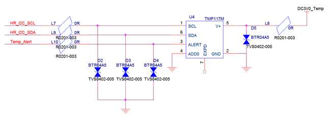
Below is the SCH.
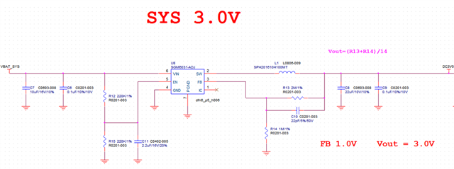
Thanks a lot.

William Z

  • William - 

    Do you know if they have tried to look at the SG datasheet? http://www.sg-micro.com/uploads/soft/20200210/1581315549.pdf  - they have a graph there which shows what you might be describing (as the startup behavior of the step down switcher). (page 5)

  • William,

    How is the 40mA being measured? What other devices share this current?

    Can you capture the event on oscilloscope?

    thanks,

    ren

  • Hi,Ren

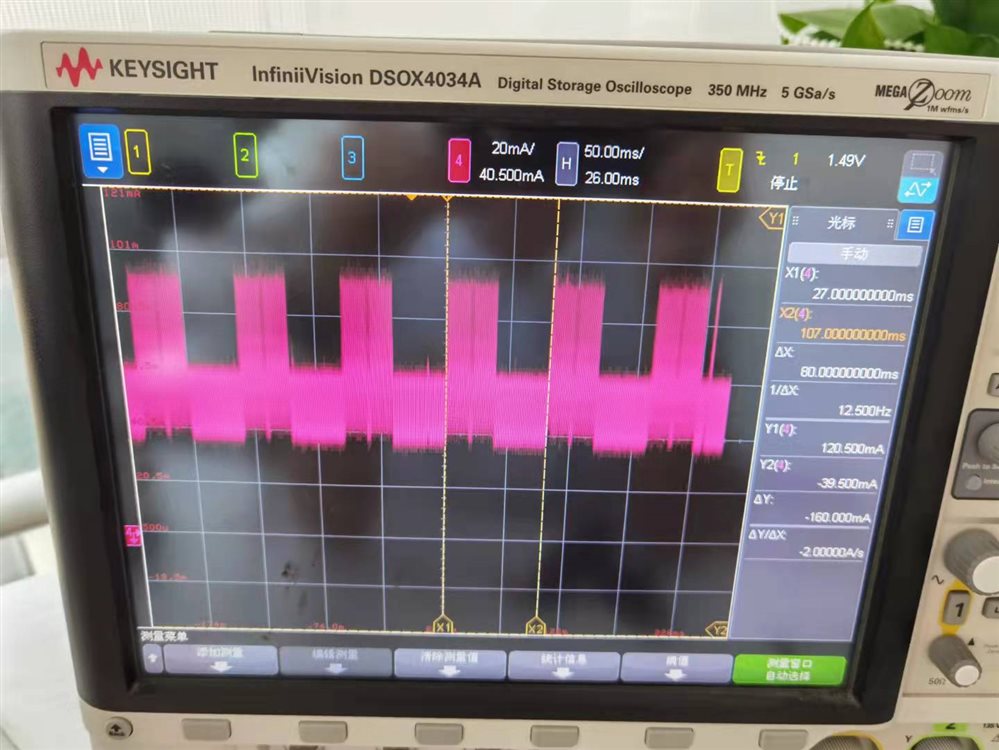
       When TMP117M is extremely hot, I measured the current at VBAT_SYS point, the value is as below

    But after restart the DUT, TMP117M is cool down,and the vbat current is down to average 15mA,then in a long period,it is very difficult to see this hot issue.

    As you konw, when we found this issue,we dare not to switch off TMP117M power supply and insert a current meter on it,because hot issue is so easy to disappear if you restart the system.

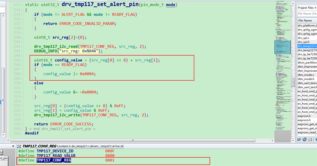
    Below is relevant register configuration,the other registers are kept as default

  • Hi, Josh

        What is your point? The graph shows the start timing characteristics,can you further explain its detail for me?

  • Dear Chao -

    the switcher has a startup behavior which seemed to match your description of the issue. You can insert current meter for your test beforehand I think and measure as Ren suggested. You should also be able to use bench supply and isolate the TMP117 with known good power supply, to cut the problem in half, as here they did not follow the SGM6031 datasheet exactly with regards to the EN pin, they are not using recommended inductor (they used one that does not even show up on the datasheet ==> https://www.sunlordinc.com/UploadFiles/PDF_Cat/20120716162212894.pdf and they swapped the feedback resistors, got the formula wrong on the schematic you shared, etc. etc.) More than likely you will find the issue is in circuit behind the TMP117, not with our device as it will draw uA not mA, so that is the clue that leads me to think what i wrote above and by troublehooting in the manner i suggested, you will find the answer. You can also change scale on the scope and I would guess you will see the frequency of the switcher in there as well.  

  • Hi,Josh

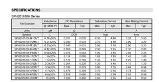
        Regarding the inductor,you got the wrong datasheet,below for your reference

      Reagarding SGM6031 VOUT formula,it is Vout=1.0*(1+R13/R14),Vout is 3.0V,which match up our test result on VOUT point.I think the schematic is correct.

    Moreover,I have confirmed  that TMP117 is so hot and I tested the temperature on it with dedicated instrument that can measure surface temperature of  devices.It is exactly TMP117 drawing for more than 40mA current,leading high temperature.

    I think it is for sure  TMP117 go into abnormal status,maybe you can give us some other suggestion.

  • Dear Chao - I would check your layout and the TVS parts to see if any are shorted (with no power applied) and change the IC if they layout is OK, but there must be some error in parts placement or the layout itself. - I think its safe to say its gone - it should never draw that sort of current.  

  • TMP117 Layout.brd

    Hi, Josh

        Please check layout file attached.

  • Chao - 

    please send a PDF or check it locally - and I meant by checking to use an Ohmmeter and the layout for the board, on your bench.   

  • Hi, Josh

      The thermal issue happened at a rate of 2%,and once rebooted,the issue will disappear soon,then you will never see it.I think it is probably related to software configuration or a bug.If the borad is shorted,we can see thermal issure easily,but in fact it is at a low probability.

    top.pdfbot.pdf

  • Chao  - 

    ok then - closing this thread. 

  • Hi,Josh

        I am wondering if any current leakage inside TMP117M is possible or not,in some circumstances,like ESD attacking on the pins,internal circuits are drawing abnormal current from VDD or I2C or Alert pins,leading to temperature rising.I think you should consult your RD team for comfirmation.

  • Dear Chao - 

    If you suspect they you are exceeding the ESD rating of the device, then you need to determine from where the ESD strike is coming and what the level is, then they need to take appropriate action, like adding ESD protection on the assembly line (wrist/foot straps, tinsel, ionizer, etc., whatever is needed)

    you can note here that the ESD protection local on the board is using a part number for which I cannot find a datasheet for - this is one thing to look into as well - BTR04A5 (plenty of unknown distributors selling, no datasheets anywhere)

    Leakage current on the TMP117 device is in the sub uA range, you described the part pulling 40mA....I would suggest here that on the unit in question, they remove all the ESD protection parts or replace with ones that there is a datasheet available for and then power the TMP117 from a known good power supply, to try to isolate the issue to a component or a part of the layout. 

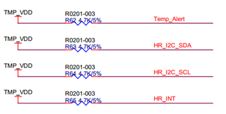
    Furthermore - you can check that you do have pullup resistors on SCL, SDA and the ALERT pins, and make sure they are of the correct value range. I did not see those on the schematic, so please check those, too. 

  • Hi,Josh


        Attached the TVS datasheet and pull up resistor of schematic.

    Btron BTR04A5.pdf

  • Chao - 

    Thanks! Let us know how the troubleshooting steps go.