This thread has been locked.

If you have a related question, please click the "Ask a related question" button in the top right corner. The newly created question will be automatically linked to this question.

AWR2243BOOST: SPI communication and rlDriverRecieveSync error

Part Number: AWR2243BOOST

Hello,  I am following the procedure given in the thread: AWR2243BOOST: mmwave Device Power on failed for deviceMap1 with error -8 in AWR Single Chip setup with Jetson AGX - Sensors forum - Sensors - TI E2E support forums

I am able to get to step 7 where HOSTIRQ is brought low and my host device begins reading the message from the AWR. Here is a wave form capture of just that:


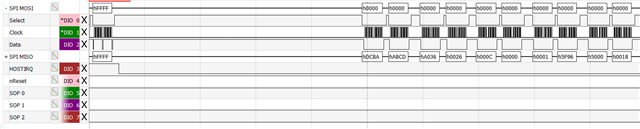
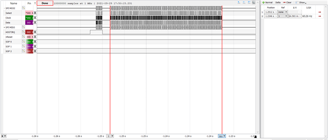
This string of message on MISO goes on for roughly 16 ms, shown here:

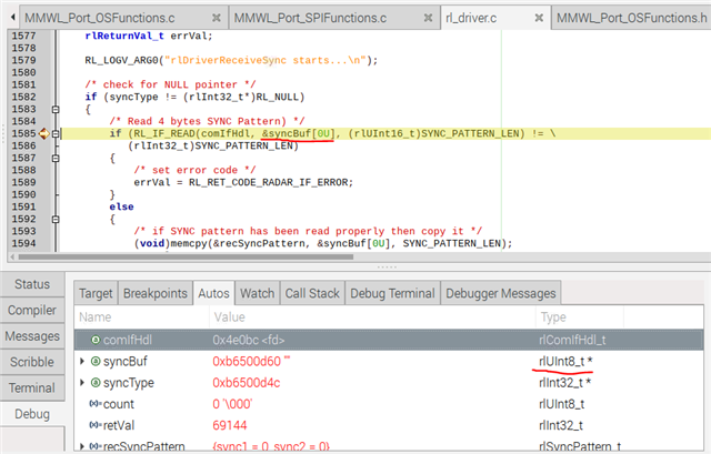
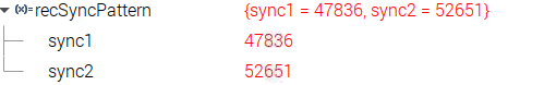
I have also discovered that rlDriverRecieveSync results in the count reaching the sync scan threshold (rl_driver.c line 1628). 

Any advice on how to proceed or why the count reaches this threshold?

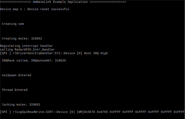
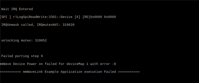
For completeness here is my terminal window after executing the application:

  • Hi,

    Looks like somehow this if condition doesn't match which later causes [  else if (count >= (rlUInt16_t)RL_SYNC_SCAN_THRESHOLD)  ] condition true.

    if (((recSyncPattern.sync1 == H2D_SYNC_PATTERN_1) &&
    (recSyncPattern.sync2 == H2D_SYNC_PATTERN_2) ) || \
    ((recSyncPattern.sync1 == D2H_SYNC_PATTERN_1) &&
    (recSyncPattern.sync2 == D2H_SYNC_PATTERN_2)))
    {
    /* set to SYNC Matched flag if H2D or D2H SYNC pattern is matching
    for big/little endian data */
    retVal = SYNC_PATTERN_MATCHED;
    }

    as per above log I can see data read in correct format, but how it is being interpreted within the application you need to debug that.

    Try to put the breakpoint within 

            while (((retVal) == (rlInt32_t)PATTERN_NOT_MATCHED) && (errVal == RL_RET_CODE_OK))  {  ..... }

    and see syncBuf or recSyncPattern for D2H_SYNC_PATTERN_1 and D2H_SYNC_PATTERN_2, this way you can find the cause of hitting count goes beyond threshold. 

    Here is working received data at this point (first asynchronous event message) for your reference-

    # INFO: Received HOST_IRQ_LOW command from device 1
    Device [1] [RD]0xDCBA 0xABCD
    Device [1] [RD]0xA036 0x0026 0x000C 0x0000 0x0001 0x5F96
    Device [1] [RD]0x5000 0x0018 0x774A 0x0015 0x0040 0x0000 0x0000 0x0000 0x0000 0x0000 0x0000 0x0000
    Device [1] [RD]0xCD8B

    Regards,

    Jitendra

  • After following your advice I have found that sync1 and sync 2 within recSyncPattern are both 0, never matching the sync pattern that is sent over spi. Could this possibly be a timing issue? The time between HOSTIRQ going low and 0xDCBA 0xABCD being sent over MISO is a little over 1 ms.

    **Update**

    So it appears the variable syncBuf that the driver is using in the RL_IF_READ call is a pointer as opposed to a buffer of data like cynsBuf, here is a screen grab of my finding:

    The usage of syncBuf and its type are underlined in red. 

    It appears the driver is using the address of syncBuf(so a pointer to a pointer) in the buff parameter of RL_IF_READ. 

    Can I get more clarification on what is going on here?

  • syncBuf is an array, and mmWaveLink passes pointer of 1st index of this array to RL_IF_READ function. RL_IF_READ is nothing but rlComIfRead callback which you have implemented in the application to read the data from SPI interface.

    Now you need to check implementation of this callback, where you need to update this memory region (array pointer) with the read SPI data.

    Looks like in the callback function data is not properly update, that is the reason that on the SPI line data is available but somehow it is not reaching to mmwavelink layer (rl_driver.c).

  • So I have found that the bytes of my read buffer are getting swapped when it is memcpy'd to the recSyncPattern as shown here:

    I have attampted to swap the bytes of pBuff(syncBuf in the driver) within my spiRead function before returning to the driver just as I did with spiWrite, however I still get the above results. Also I am using spidev ioctl SPI_IOC_MESSAGE transfers to achieve my spi communication. It looks right for the most part on the logic analyzer as mentioned in my previous post above. I am at a loss on what to do from here, any advice would be welcome.

  • Looks like each 8bits are swapped here by your Host SPI interface.

    Please check in your SPI driver for how data copy is set while it receives from external line to internal FIFO/RAM

    MSB or LSB first, any swap setting applied there.

    what is SPI data format x data word length? it should be 16 bits not 8 bits.

    On physical line data is correct 0xABCD and 0xDCBA but while Host SPI interface copies those to application RAM, each 8bits are swapped. Please check your SPI driver in detail.