This thread has been locked.

If you have a related question, please click the "Ask a related question" button in the top right corner. The newly created question will be automatically linked to this question.

AFE3010-EVM: Change to DC relay(5V)

Part Number: AFE3010-EVM
Other Parts Discussed in Thread: AFE3010

Hi,

My customer is using AFE3010 for the thermoStats application. They have the AFE3010 EVM to do the validation which works fine. However, they will need to change to the DC application, which is to use DC relay(5V). 

here is the datasheet for the relay. 

DC relay(5V): GC 16A 2020 V2.0.0.pdf

May I have your support to base on the AFE301 EVM to give the recommendation on the parts that need to be changed in order to work with DC relay (5V)? Thanks.  

  • Hey Jack, 

    I am looking this over and will respond within a couple hours.

    Best,

    Peter

  • Hey Jack,

    I assume the AFE3010 will still be sensing faults on an AC line voltage?

    Anyway, I believe using this relay could still work as it is rated for a high voltage. If the SCR pin is to drive the coil directly, then relay coil needs to be common with the AFE3010 GND pin with the SCR driving the other pin. Since the SCR driver is a current source, you will need to add some current-limiting resistance. The SCR driver is rated to 3mA with a 1V output, so I would shoot for limiting SCR output current to <1mA, so the coil voltage is sufficiently greater than the 2.25V coil pickup voltage. Unfortunately, as the SCR driver is a current source (with variable voltage) and the relay is controlled with a voltage that is greater than most coil pickup voltages shown in datasheet.

    For reference, from my testing with SCR pin driving an SCR with 549 Ohm of resistance, the output current is about 1mA with SCR pin voltage at around 2.5V and the SCR gate voltage at around 1.95V. 

    Customer may want to consider using the SCR pin to drive a transistor amplifier that outputs a higher voltage that will consistently supply the coil with the same voltage every time. For example you could place a resistor divider off the VDD (20V) rail and once SCR goes high, you could use this signal to turn on a transistor that short the divider voltage to the coil input.

    Hope this all makes sense.

    Best,

    Peter.

  • Hi Peter, 

    Thank you for your support. I have few questions to check with you. 

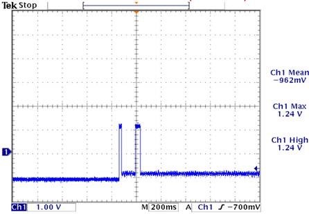
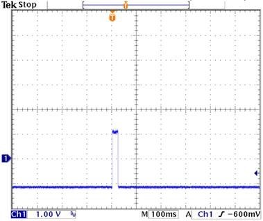
    1. In the EVM user guide, it says that without a solenoid, a 10k resistor (resistance similar to solenoid) can be used. However, when we used the solenoid, we saw two pules from SCR. And when we use 10k resistor, we only saw one pulse from SCR. Is that an expected behavior?  If so, what will be the reason?

    Solenoid(AC Relay) connect from HOT to D2-A  SCR pin status:

    10K(5W) Resistor connect from HOT to D2-A  SCR pin status:

    2. Does TI have the reference design for using the DC relay instead of Solenoid? 

    Thanks.  

  • Hey Jack,

    What was the system condition when the scope shots were taken? I assume there is a a resistive fault and you are powering up system.

    Was the solenoid used actually breaking open a load switch (and thus stopping the fault)?

    How many times did they see this behavior?

    Can customer try with a <200-Ω resistor? Unfortunately, 10kΩ is not accurate series resistance for most solenoid so using the 10kΩ is not very realistic even though its functional.

    To me, the first image with two pulses (using solenoid) looks like a continuous self-test fail (SCR fires ~150 ms after power up). Does customer see the ALARM LED blinking at all when this happens?

    We do not have a reference design for this, but it should be a straight-forward design. Just make sure to limit output current from SCR driver, relay coil gets the proper turn-on voltage, and that the relay has the appropriate voltage rating. There is some additional mechanical design needed on how to physically close the load switch of course as well.

    Best,

    Peter

  • Hi Peter, 

    Thanks for the reply. 

    I have a question regarding the transformer. In AFE3010 EVM, it was using GALAXY TRANSFORMERS AS5859-04. Is there any concern to use different vendors "ex. C.A. Spalding" transformer with the same spec. which is also AS5859-04? 

    Thanks.   

  • Hey Jack,

    No concern here of using different vendors, but at the least the number of turns should approximately be same. They can differ a little, but there might need to be some adjustment to R13, RFB, and/or Rin depending on which CT has the dissimilar turn count and or impedance. So for the primary fault current CT (1000 turns), if the actual number of turns is less, this mean less current gain, thus you need to increase RFB in order to increase gain of internal current-feedback amplifier and restore the overall fault signal gain.

    If the other Neutral-ground CT differs in number of turns (300 instead 200 turns), then this will mean increased inductance and inductive kickback for the internal output driver of the NG_OUT pin. The absolute voltage value of this pin (with respect to device ground) cannot go under -0.3V, so either R13 will need to be increased or a clamping Schottky diode should be placed at NG_OUT pin to help protect it from -0.3V and a large in-rush of current from turning on any internal ESD body diodes.

    This type of fine-tuning for the specific current transformer chosen is explained in section 8.2.2 of datasheet.

    Sincerely,

    Peter

  • Thank you for your support and the detail explanation, Peter.