- Ask a related questionWhat is a related question?A related question is a question created from another question. When the related question is created, it will be automatically linked to the original question.
This thread has been locked.
If you have a related question, please click the "Ask a related question" button in the top right corner. The newly created question will be automatically linked to this question.
Hello
I have got the IWR6843AOPEVM and I have done the following:-
1.) Installed the required drivers and uniflash
2.) Successfully flashed the out of box demo bin to the EVM
3.) Change the mode to functional, manually reset the board. (Have tried unplugging and plugin back too)
4.) Able to connect to the board from the visualizer and send over the config. (See screen below)
5.) However when I switch to Plot tab, I don't see any data being plotted. I have repeated steps 1-4 a few times with no luck.
Am I missing something basic here?
Thanks
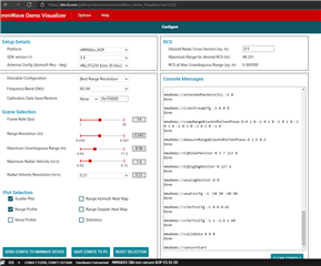
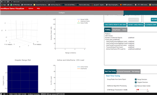
Here's some additional info

When I connect to COM4 from a terminal program and reset the EVM I do see the demo startup string in the terminal.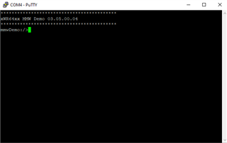
Hi Jameel,
Thanks for reaching out with your question.
Did you flash the correct binary file to your EVM. Since you are using the AOP board you want to make sure you are following these instructions and flashing the xwr64xxAOP_mmw_demo.bin file to your EVM.
Another thing to check is if your AOP board is the new ES2.0 silicon which you can read more information about in the link I sent above. Some older AOP EVM boards may not be compatible with the visualizer demo.
Additionally here was another TI E2E post several months ago where based on what version of AOP board you have, you may need to use a different SDK or visualizer version. e2e.ti.com/.../iwr6843aopevm-iwr6843aopevm-demo-visualizer-version
Have you tried any other demos or labs with your EVM or is this the first one?
Thanks,
Alex Chan
Hello Alexander
Thank you for the reply.
1.) I have checked time and again that the correct bin is flashed.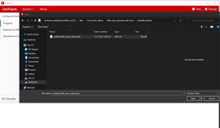
2.) Flashing is successful
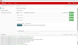
3.) CGF and Data port is connected ok and config data is sent over
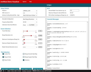
4.) But plot screen still shows nothing
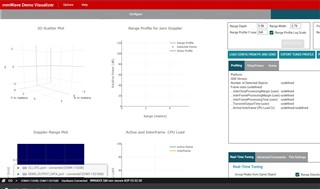
I have tried the below:-
1.) Re install the CP2105 drivers (to rule out any USB issues)
2.) Flashed the vital signs demo and also same issue
3.) Flashed the gesture/people counting which also has the same issue.
I am just short of trying it on another machine.
Am I missing something very basic here? After sending the config data over the CFG port, should I expect some data on the DATA port?
Any help in the right direction is very much appreciated
Thanks
Alex.
Hi Jameel,
Can you verify that your EVM is Rev F? It should have Rev F written in white letters on the board.
Please take note of the following LEDs you can find in the assembly drawing as well as refer to the schematic.
LD1 - 5V Led indicator
LD2 - 3.3V Led indicator
LD3 - User LED
LD4 - USB Enumeration LED
LD5 - Reset LED
Can you also see if you have the same green LEDs light up as follows.
On initially plugging in the EVM there should be the following LEDs on (LD1, LD2, LD5). When you press the RST button LD5 should blink.
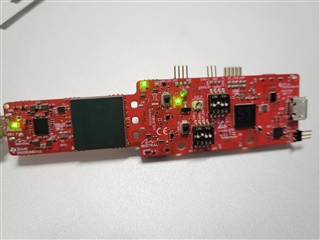
After loading the cfg you should see the following LEDs on (LD1, LD2, LD3, LD4, LD5).
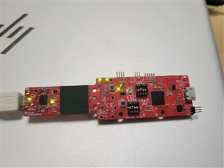
Can you double check to see if the LEDs are working as shown above.
Another thing you can look into is running debug mode on the EVM. https://dev.ti.com/tirex/explore/content/mmwave_industrial_toolbox_4_8_0/labs/common/docs/software_setup/using_ccs_debug.html
This can be a useful way to debug the EVM to see if there are any issues.
Thanks,
Alex Chan
Hello Alex
Thank you for clearly explaining, I had checked everything as mentioned and was having the same issue. Finally I changed laptop and it worked. Look like there might be some issue with the USB port, but I have been using this for other embedded dev purposes with no issues so far. Anyways truly appreciate for pointing in the right direction towards a resolution.
>Another thing you can look into is running debug mode on the EVM.
I only have the IWR6843AOPEVM, for debug mode would I need MMWAVEICBOOST board right?
Regards
Jameel
Hi Jameel,
Glad to see you got it working and sorry for not thinking of recommending something like switching laptops sooner. I will keep that in mind for future debug issues.
Yes you are correct debug mode you cannot use the standalone IWR6843AOPEVM and would need the MMWAVEICBOOST. In reality since you were just using the default bin files it may not have been very helpful. The debug mode is helpful once you start modifying or changing the bin files from default. Then once you start flashing it onto the EVM it is hard to know what is going on with the EVM and the debugger can provide some feedback.
Thanks,
Alex Chan
Hello Alex
I only got the AOP EVM to quickly evaluate the chip performance. My key areas of focus are the following labs
-3D People Counting
-Fall Detection
-Vital signs
I am planning to get the MMWAVEICBOOST carrier board for code modification and debugging, my question is for the above labs would I need the ODS or ISK board or would the APO EVM is sufficient?
Thanks again.
Jameel
Hi Jameel,
The AOP EVM will be sufficient for all of those key areas of focus you had mentioned. All of the boards boast the same base characteristics like 4 receive (RX) 3 transmit (TX) antenna with 120° azimuth field of view (FoV) and 120° elevation FoV. Here are a few of the differences and you can see in the image that AOP and ODS overlap in the same general support areas.
We have labs/experiments for all of those topics you had mentioned in the resource explorer.
Thanks,
Alex Chan
Hello Alex
So could I infer that the AOP and the ODS are very similar in terms of performance?
Then I will order a BOOST and an ISK to try out the different distance/angle combinations.
Regards
Jameel