This thread has been locked.

If you have a related question, please click the "Ask a related question" button in the top right corner. The newly created question will be automatically linked to this question.

TDC1000: ultrasonic transducer output_TDC1000 Receiver configuration related

Part Number: TDC1000

Shall we add any biasing circuits or any additional configuration between the ultrasonic sensor output and the Receiver terminal of the TDC1000 IC.

We are getting bipolar output of the ultrasonic transducer. So we want to make a threshold addition(By Op-Amp based biasing circuits) in the output of the ultrasonic transducer before the TDC1000 IC receiver Input pin.

Is it possible in this IC

  • Hello,


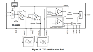
    The TDC1000 allows the user to have full access to the signal path, so it will be possible to add additional components to create an external threshold via an amplifier. I recommend verifying the functionality of the TOF measurements with the TDC1000, then adding the thresholding circuit. This will make the setup process a bit easier and reduce complexity if you require any debugging.


    The TDC1000 datasheet section 8.3 details the receiver path in further detail. Datasheet linked here: TDC1000DS

    Please let me know if you have any questions,

    Thank you,

    Jacob

  • Hi Jacob,

    Thank you for your Inputs.

    My question is, Is it possible to add the additional circuits at the RX1 & RX2 pin before the MUX.

  • Hello,

    Yes, you can place analog circuitry before the RX1 and RX2 pins if desired. Note, the receive signal amplitude will be nearly indistinguishable from noise in most cases. Therefore, it is usually recommended to place any type of external thresholding circuit after the gain/filtering stages to improve the SNR of the return echo. 

    Please let me know if you have any questions,

    Thank you,

    Jacob