This thread has been locked.

If you have a related question, please click the "Ask a related question" button in the top right corner. The newly created question will be automatically linked to this question.

LDC0851: Output always high

Part Number: LDC0851

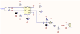
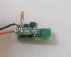
We use the  LDC0851HDSGR in a stacked coil setup. The output however never goes low indicated that metal has been detected. 

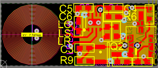
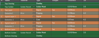
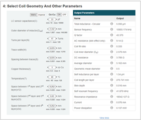
I used the webench tool to generate the coil and select a capacitor value. I've added the schematic, the pcb layout and the stackup. 

The coil diameter is 7.75mm, the tracks have a width of 0.076mm and a clearance of 0.076mm. Any suggestions on how to fix this would be helpful. 


  • The parameters given by the tool we used to generate the coil. 

  • Hello, 

    I have a few questions for you on this. 

    • What is the metal target's distance to the sensor (min and max if applicable)? 
    • Have you tested with any other resistors for R8 (ADJ pin)? 
    • Is there any other metal nearby in your application/testing that is not the target? 

    Best Regards, 

    Justin Beigel

  • Hi, 

    The target is 3mm.

    We have not yet changed the value on this design as the problem is no the range that it detects something, but that the output is always high. 

    Ww have no metals nearby while testing. The following image is however how the setup looks, the top PCB has the regulators on for the design and we had to do this stackup to fit into the enclosure. I don't believe that the top PCB affects the coils as I have tested it with the top PCB removed. 

    Regards

    Douglas

  • Hello Douglas, 

    Thanks for the clarification. I have a few more follow up questions for you. 

    • Is this happening with multiple devices or just one? 
    • Can you probe the via for the reference coil and check the sensor oscillation and frequency with an oscilloscope? 
    • Have you gone through the LDC0851 - Troubleshooting app note yet? 

    Thank you, 

    Justin Beigel

  • Hi Justin, 

    I have gone through the trouble shoot app note, that is how I ended up with the current design as I saw our previous design wasn't supposed to work, but did. It was 2 coils on separate PCB's but used too much power, so we tried the single PCB stacked coil setup, with more coils and the smaller cap as the webench tool showed it would use less power. 

    It is happening on multiple devices.

    I was out of office this week and will try and measure the reference coil as soon as I can. 

    Regards

    Douglas

  • Hi Justin, below is the scope of the LR and LS respectively. 

  • Hello, 

    From your screenshots, there is a considerable frequency difference between the sensors. The reference (13.89MHz) is higher than the sensor (11.76MHz) which could be the cause of your issue. The frequency of the sensor is tied to the inductance of the coil and the reference being offset to the sensor this much can cause for the output to never switch regardless of target distance. 

    I don't see anything in your layout that would obviously cause the difference. Your traces seem relatively matched from the photo with the only difference being a via. 

    Best Regards, 

    Justin Beigel

  • Hi Justin, 

    I went back and measure again. This time I saw that the frequency changes between 13MHZ and 15MHZ. The design is for 16MHZ.

    Any ideas on what might cause this or what I can do to debug this?

    I measured this on the pins of the IC. 

    LS:

    LS Mixed signals

    LS Isolated signal 1

    LS Isolated 2

    LR mixed signals

    LR signal 1

    LR Signal 2

  • Hello, 

    The capacitance on an oscilloscope probe can have an effect but it seems like you are using the same probe for both channels and that wouldn't account for the difference between the coils. Your traces seem to have slight differences between the device and the coils (a via and a slightly different length) but it is not enough to make this much of an impact in the frequency. 

    Is the frequency consistent across your different units? 

    Best Regards, 
    Justin Beigel

  • Hi Justin, 

    Yes, it looks the same across all our units. 

    Regards

    Douglas

  • Hello Douglas, 

    Thank you for confirming. If you look at the individual layers of your coil design, you can try to find any places where the reference coil is different from the sensor coil. Would you be able to share the layout file? 

    Thank you, 

    Justin Beigel

  • layout.PcbDoc

    Hi Justin, 

    We used the coil generated by the Webench tool. I have added the layout. 

    Regards

    Douglas

  • Hello Douglas, 

    Thanks for sharing the layout. I have a few follow up questions for you to help debug this further. 

    Can you measure the Rp of both sensor and reference coils? The snoa936 app note has instructions on how to do this. 

    I would expect it to be slightly different due to the slight difference in trace lengths and the via on the reference. 

    Additionally, can you do some testing with the LDC0851EVM coil in your system in place of your LDC0851 portion? It would be best if you can just swap coils but I don't think that would be easy with your board. 

    Lastly, if you change the capacitor to change the frequency of the sensor, is the frequency shift still the same proportion between reference and sensor? 

    Thank you, 

    Justin Beigel

  • Hi Justin, 

    I'm sorry that I could only get back to you know. 

    We unfortunately do not have the necessary tools to measure Rp and we do not have the LDC0851EVM coil.

    I have however changed the capacitor to 82pF and measured the following on the Sensor and Reference coil pins:

    LS:


    LR:

  • Hello Douglas,

    It appears that by changing the capacitor to 82pF the LS and LR frequency delta has reduced. Is the change in capacitance acceptable for your application and are you able to detect the target ? 

    For RP measurement technique 4 would be best suited if you don't have access to network analyzers. A bench top instrument can work here. The accuracy may not be achieved with this approach. 

    Also, LDC0851EVM can be purchased and here is the link 

  • Hi Arjun, 

    We're still unable to detect the target. 

    To you mean point 4 as in method 3? I do not see a method 4 in the linked app note. 

    Regards

    Douglas

  • Hello Douglas, 

    Yes, method 3 with the signal generator is what Arjun is referring to. Since the capacitor change led to a closer frequency between the two coils, then there may be more parasitics involved in your design than anticipated. You could try increasing the capacitor again or consider changing the coil design. if you change the coil design, you could also use the EVM to test the coil change before running a new revision of your board.

    Best Regards, 

    Justin Beigel

  • Hi Justin, 

    I tried increasing the capacitor to 100pF and it still didn't work. 

    Would it be possible to send you one of our boards? We don't have the equipment to measure Rp.

    Regards

    Douglas

  • Hello Douglas, 

    Since the delta seems to be frequency dependent. I would expect that as you get lower in frequency, the two signals would become closer to the same frequency and you would have a better chance at seeing a switch output but increasing the capacitor much more will start to cause current limitations from the part. This is why I think there may be some merit to changing the coil design to a lower frequency. Is a coil redesign something that you can consider for this application? 

    For the sake of Rp, measuring this is a good determination to see how the coil differs from the design. However, I don't think it is worth shipping in the board to measure. 

    Best Regards, 

    Justin Beigel

  • Hi Justin, 

    I will try and see what happens if I increase the cap even more. 

    We're rather far in into our development funds, so it is not ideal to to a redesign at the moment, but if it needs to happen we will have to do it. 

    The reason I used this design is because our previous coil design for some reason used too much power and I saw this coil design used less power according to the webench tool. 

    Regards

    Douglas

  • Hello Douglas, 

    Do let us know how the increased capacitance goes but I would expect you to run into current issues somewhere around 150-200pF. 

    Best Regards, 

    Justin Beigel

  • Hello Douglas, 

    Just checking in. Did a different cap value help this issue? 

    Best Regards, 

    Justin Beigel

  • Hi Justin, 

    I completely forgot to get back to you. 

    I'm embarrassed to say that the problem was that the reference and sensor coils were swapped and we've been trying to detect metal from the reference coil side. 

    Everything is working as it should now.

    Regards

    Douglas