This thread has been locked.

If you have a related question, please click the "Ask a related question" button in the top right corner. The newly created question will be automatically linked to this question.

TIDEP-01012: Help for external triggering on cascade radar

Part Number: TIDEP-01012
Other Parts Discussed in Thread: LMK00804B, TDA2

Dear TI team, 

I am working on an application where we want to trigger the radar externally. 

I saw the post : https://e2e.ti.com/support/sensors-group/sensors/f/sensors-forum/878236/tidep-01012-cascade-imaging-radar-sync-log-with-camera

where it is recommended to modify some resistors but I do not know what are the other necessary steps to achieve external triggering. 

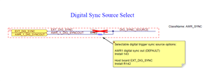
  • Should I just change the trigger config of the master in the lua file from software to hardware ?
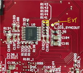
  • The post above mentioned a part U8 LMK00804B, while I can see the chip, I do not see where to connect a wire with the trigger. Is there a specific place to connect this wire or should I also solder it ? 
  • Regarding the acquisition, if I enable it correctly, what should I modify in the Lua code (for example the capture one) ?

Best regards, 

TF

  • Hi TF,

              As mentioned on the link too there are 2 ways to feed the hardware trigger on the MMWAVE CAS RF EVM. One if from the Primary radar device which is AWR1. The primary device feeds to buffer which then feeds to all radar devices including primary device itself. this is the default configuration on board.

    The other option which is EXT_DIG_SYNC connected to HOST(for example this signal is coming to the TDA2 MMWAVE_CAS DSP EVM mating connector). 

    If you intend to feed it from some external other then the arrangement made, you can explore on TP1_1.

    Once you feed it externally you will have to also ensure that Primary device trigger is also moved to hardware(from default software).

    Capture or acquisition should not demand any change.

    Regards

    Abhed

  • Hi AM, 

    Thanks for the quick answer. I have some follow up questions.

    If I modify the resistors as explained on the linked post, and set the trigger to hardware in the LUA code for the configuration, is it correct to say that it should work with no other modification ? 

    Regarding the capture script in LUA, I guess I should remove the parts that does the software trigger ? Or will it be automatically ignored because of the changed configuration with the hardware trigger ?

    Does the trigger controls the start of frames (of several chirps defined by the lua code) or does it control the trigger of each chirp ? 

    Finally, where can I access the EXT_DIG_SYNC signal on the board to "plug" my external trigger ? Is there a dedicated port ?

    Best regards,

    TF

  • Hi TF,

               Yes. 

    Once you make the modification sin hardware for hardware trigger then the script should also be updated accordingly to configure the trigger mode in device. 

    DIG SYNC is used for Frame trigger. 

    The TP1_1 is connected to AWR_1_DIG_SYNCOUT. 

    As a suggestion you can TRY to connect on this TP and mount the resistance as shown below(remember to open R143), other wise you can solder the resistance on R142 one pad itself.