This thread has been locked.

If you have a related question, please click the "Ask a related question" button in the top right corner. The newly created question will be automatically linked to this question.

PGA460-Q1: Device setting and some other questions

Part Number: PGA460-Q1
Other Parts Discussed in Thread: PGA460

Hi, TI team,

I have some questions while using PGA460 kit, those are divided into 2 parts as follow:

Part1: About Device setting

1. There are four different kinds of parameters could be setting to make the echo data in a suitable range: Burst Pulses, Curent Limit, Digital Gain and TVG, may I have your suggestion that (the order) which one(s) will be tuned first, and which one(s) will be the last?

2. The relationship between the Burst Pulses and Current Limit? Because for my experience, the value of the main peak become quite similar while enlarge (2x for e.g.) either the Burst Pulses or Current Limit. Or this results are just the coincidence?

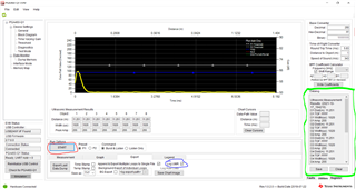
3. I could only get 128 sampled data totally while exporting the Echo Data Dump data as txt or csv file. How can I get more samples?

4. I don't know how to use "Log UMR", is there any document describing related setting? (I check this while exporting EDD but didn't work!)

Part2:

1. Could you please explain more details about the "Burst Pulses"? How those components within in the transducer works to make one period?

(https://e2e.ti.com/support/sensors-group/sensors/f/sensors-forum/962619/pga460-q1-burst-pulse-meaning?tisearch=e2e-sitesearch&keymatch=%2522PGA460Q1%2522%2520burst%2520pulse#)

2. According to the figures from chapter 4.2 and 4.3 in "slaa732__PGA460_HW_SW_Optimize", are there any formula can describe the relationship between pulse count and bursting time (or ring-dacay time)? (It's obvious to see that both numbers of pulse count and current limit decide the bursting time (or ring-dacay time).


Very thankful of reviewing my questions.

Shihyu.

  • Hi Shiyu,

    1. The order at which Burst Pulses, Current Limit, Digital Gain and TVG are set doesn’t matter as long as they are set before the burst and listen operations are initiated. The following video provides an example of configuring these parameters: https://training.ti.com/pga460-ultrasonic-sensing-how-set-and-install-evm?context=1128182-1128152
    1. The current limit feature is mainly for transformer-driven modules and is a way of controlling the peak-to-peak driver voltage at the transducer. Generally, the larger the driver current limit at the primary side of the transformer, the larger the excitation voltage swing at the secondary (transducer) side of the transformer, which would result in a stronger signal.  Adjusting the pulse count affects the transducer excitation length and also results in a stronger echo strength, regardless of whether a direct-driven or transformer-driven module is used. Sections 5.2 and 5.3 of the below application note provides more info on how pulses and the current limit affects the echo strength: https://www.ti.com/lit/an/slaa732a/slaa732a.pdf
    1. The data-dump memory on the device stores a maximum of 128 bytes. Echo data is down sampled to allow capturing of the complete recording interval. The down sampling amount depends on the record time-length parameter for the preset of interest set by the P1_REC and P2_REC bits in the REC_LENGTH EEPROM register. During the process of down-sampling, a peak hold function is performed and therefore only the highest level values after down-sampling are stored in the data-dump memory. If you need more than 128 samples for a burst period, another option is to use direct data burst mode, which is described in Section 7.3.7.2 of the PGA460 datasheet.
    2. You can enable this by performing the following steps:
      1. Clicking the “Log UMR” checkbox (circled in blue below) in the data monitor tab.
      2. Clicking “Start” (circled in red below).
      3. Clicking on the “Utilities tab on the bottom right”. The results will be in the “Datalog” textbox (circled in green below).  If you want to export this to a text file, you can click the “Save” button below the Datalog screen.
    3. There isn’t an exact formula for the decay time.  We recommend using the ultrasonic measurement results to view the decay time and then tune the system to reduce this decay time based on your short-range sensing requirements.  The below video has more info on how to perform this tuning:

      https://training.ti.com/ti-precision-labs-ultrasonic-sensing-ultrasonic-transducer-tuning?context=1139747-1139746-1147829-1147821

    Regards,

    Mekre

  • Hi, Mekre,

    Thanks a lot for your reply, those are really clear and helpful!

    Shihyu.