This thread has been locked.

If you have a related question, please click the "Ask a related question" button in the top right corner. The newly created question will be automatically linked to this question.

AWR1843BOOST: PCB Design

Part Number: AWR1843BOOST
Other Parts Discussed in Thread: AWR1843,

Hi team,

We are designing new radar with awr1843 chip. I looking your references PCB design files.

figure 1

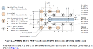
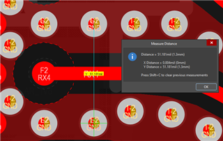
This files tells must be A=871 um for RO4835. But i look AWR1843boost PCB on Altium designer and measure A distance. A=1.3 mm. This PCB also RO4835.

figure 2

Well, i will manifactured new PCB with RO3003. This A distance should be change? Any documantation is there for AWR1843 ?

Thanks 

Hasan

  • Hello Hasan, 

    Please give us some time to analyze your concern. We will get back to you with an update by tomorrow.

    Hope that's okay. 

    Regards,

    Ishita

  • Hello Hasan,

    Thank you for pointing this out. At some point in time, this antenna design was ported from Cadence to Altium, and also has been ported across multiple different designs and I think these distances may have accidentally been modified during these porting processes. Please follow the recommended distance provided in the app note. It seems like these changes have not significantly impacted the performance, but they can have an impact on the desired impedance.

    The app note states the dimensions needed for RO4835 vs RO3003, so you can refer to the values in the app note for RO3003 material.

    Regards,

    Adrian