This thread has been locked.

If you have a related question, please click the "Ask a related question" button in the top right corner. The newly created question will be automatically linked to this question.

AWR1843BOOST: Detected object by the radar sensor is resolved as two separate objects.

Part Number: AWR1843BOOST
Other Parts Discussed in Thread: UNIFLASH, AWR1843

Dear E2E community,

I am using the AWR1843BOOST board to evaluate its performance as an on-board drone (quadcopter) radar solution. For the test purposes the board is attached to the drone frame facing forward in the flight direction (slightly inclined by 10° upwards). The drone then multiple times was guided to intercept a static hovering DJI Phantom 4 drone. The DJI drone was detected by radar, but after plotting the logged data, it was often observed that the detected drone in some frames "splits" in two separately detected objects, while the real target should be a point in the middle between those 2 detections, please refer to plots below:

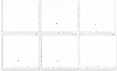
Up to frame 3314 the drone is detected correctly, but then it splits in separate points and in frame 3315 two clusters of 2 points each are detected, while actually the drone should be in the middle. There have been similar issues also at up to 10 meter ranges. Here is also a log with with detected object coordinates + velocity:

And those are the radar config parameters used (data captured over UART). The parameters have not been tuned much specifically, so perhaps the issue lies there:

% ***************************************************************
% Created for SDK ver:03.02
% Created using Visualizer ver:3.5.0.0
% Frequency:77
% Platform:xWR18xx
% Scene Classifier:best_range_res
% Azimuth Resolution(deg):15
% Range Resolution(m):0.039
% Maximum unambiguous Range(m):31.44
% Maximum Radial Velocity(m/s):2.5
% Radial velocity resolution(m/s):0.04
% Frame Duration(msec):100
% RF calibration data:None
% Range Detection Threshold (dB):15
% Doppler Detection Threshold (dB):15
% Range Peak Grouping:enabled
% Doppler Peak Grouping:enabled
% Static clutter removal:disabled
% Angle of Arrival FoV: Full FoV
% Range FoV: Full FoV
% Doppler FoV: Full FoV
% ***************************************************************
sensorStop
flushCfg
dfeDataOutputMode 1
channelCfg 15 5 0
adcCfg 2 1
adcbufCfg -1 0 1 1 1
profileCfg 0 77 6 7 200 0 0 20 1 992 5166 0 0 30
chirpCfg 0 0 0 0 0 0 0 1
chirpCfg 1 1 0 0 0 0 0 4
frameCfg 0 1 16 0 100 1 0
lowPower 0 0
guiMonitor -1 1 1 0 0 0 1
cfarCfg -1 0 2 8 4 3 0 15 1
cfarCfg -1 1 0 8 4 4 1 15 1
multiObjBeamForming -1 1 0.5
clutterRemoval -1 0
calibDcRangeSig -1 0 -5 8 256
extendedMaxVelocity -1 0
lvdsStreamCfg -1 0 0 0
compRangeBiasAndRxChanPhase 0.0 1 0 1 0 1 0 1 0 1 0 1 0 1 0 1 0 1 0 1 0 1 0 1 0
measureRangeBiasAndRxChanPhase 0 1.5 0.2
CQRxSatMonitor 0 3 19 125 0
CQSigImgMonitor 0 123 16
analogMonitor 0 0
aoaFovCfg -1 -90 90 -90 90
cfarFovCfg -1 0 0 30.99
cfarFovCfg -1 1 -2.51 2.51
sensorStart

Would appreciate any help/inputs.

Best regards,

Vadim.

  • Hi,

    Are you using the latest version of the SDK 3.5?

    It is very difficult to provided an explanation for this behavior. Do the two detections appear only for a few frames?

    I will further check with the systems team if they have an explanation for this behavior

    Thank you

    Cesar

  • Hi Cesar,

    For the example shown I had a custom C++ code on an ARM microcontroller, which utilizes 1 UART pair for CLI config by sending the commands I posted above and the radar data comes over MSS_Logger to another UART RX port (bypassing the XDS 110 by removing resistors). So not using the SDK directly.

    Another example done even earlier, here the board was set on a table and the DJI drone was flying in front of it (same radar config). Board connected via USB to PC and data parsed with Matlab (still with XDS connection and similar to the python script provided in the SDK):

    So the two detections happen sometimes for 3-5 frames, then they can merge back to one point. For the majority of time the drone is detected correctly and those two detections happen mostly when the drone flies perpendicularly towards or away from the radar.

    The config .txt was exported after the very first tests with mmWave Visualizer, there I believe I could not run 3.5 so used the 3.2 version. With Visualizer live plotting I didnt observe the detections much, so can not tell if those double detections would occur there too.

    I have not done any prior radar calibration with a corner reflector or similar, just out of the box flashed the board with latest Uniflash firmware.

    Kind regards.

  • Thank you for additional details

    I have a better understanding.

    I think there are several possible reasons to this behavior

    1) There is some bug in the sw that causes this behavior

    2) There is some multi-path reflection that causes this behavior

    In order to debug this I think we should try the following

    1) Try to run SDK 3.5 binaries and check if problem is still there.

    2) collect raw data and analyze in matlab (this will require a DCA1000 board)

    This does not look to be a calibration issue due to the symmetry.

    Thank you

    Cesar

  • Hi,

    thanks for the proposed solutions. I do not posses a DCA1000 yet, so checking raw data is not an option for now unfortunately. 

    Sorry, what do you mean by running the SDK 3.5 binaries? Do you mean flashing the AWR with mmwave_sdk_03_05_00_04\firmware\radarss binaries via Uniflash? If so, I need to put the resistors back for XDS 110 and can get back to you soon after.

  • No,


    The demo binaries are the following


    C:\ti\mmwave_sdk_03_05_00_04\packages\ti\demo\xwr18xx\mmw\xwr18xx_mmw_demo.bin


    Since you are not familiar with this file, did somebody else flash it on your board or are you using the one that was flashed when you purchased the board?


    Anyway, flashing this file will provide the latest demo.


    Thank you

    Cesar

  • Hi Cesar,

    thanks for the tip. I will flash the latest demo, do flight tests and evaluate results, but I will be able to update you here in 2-5 days, so leaving this thread open till then.

    Kind regards.

  • Thank you

    Cesar

  • Hi Cesar,

    sorry for a later response than expected. I have captured new data with the xwr18xx_mmw_demo.bin firmware. Unfortunately, the same problem still persists. For better reference see this time attached videos. In first video the radar is using very similar config to the one I posted originally, link to youtube:

    www.youtube.com/watch

    I made another recording, where I activated TX3 for elevation (z) measurement. Youtube link:

    www.youtube.com/watch

    In the second video you can see how the drone is separated in two point clusters in a different manner.  

    Here is one of the frame with detected object info on the left. Points 3 and 5 make no sense based on their z values, which are below ground level. Could you confirm whether the issue still lies within the firmware or if those are indeed multipath reflections (3 and 5 could be due to reflection from ground, but I see no reflection path for 6 and 4, those points also are not quite showing the drone location correctly).

    Some more pictures below for setup reference, also you can see that mmWave Visualiser shows similar issues.

    Kind regards

  • Thank you

    Were you able to upgrade the demo code to the latest version?

    Thank you

    Cesar

  • On board flashed is the latest demo firmware. mmWave Visualizer is also using the latest version. The MATLAB script is just sending the UART config and then capturing UART data, Im not using the demo C++ code provided in SDK, but as I understand that should not be the issue, the way AWR1843 is addressed and configured is still the same. I also used the exported configs from the Visualizer which worked there.

    Also videos are there now with updated links (slight delay since I manually synchronised on a sound cue).

    Kind regards

  • I just wanted to make sure that you have flashed the latest binaries shown below and that you see the same issue.

    C:\ti\mmwave_sdk_03_05_00_04\packages\ti\demo\xwr18xx\mmw\xwr18xx_mmw_demo.bin

    Thank you
    Cesar

  • Hi, yes that's what I have done. And the issues are still the same.

    Kind regards

  • Thank you,

    I am able to see the youtube video. The behavior is definitely not correct.

    We will need more data points to understand the behavior. The best would be if you can capture raw data.

    Would it be possible to try the following configurationprofile_2d_usrr_80m_128loop.cfg

    It is for 80meters max range

    Thank you

    Cesar

  • Hi, thank you, I will capture some data this week with your configuration and get back here. It will be processed data as I do not possess a DCA1000 yet.

    Best regards

  • Thank you

    Looking at the GUI and check if you still see the two symmetric detections will be sufficient

    thank you

    Cesar