This thread has been locked.

If you have a related question, please click the "Ask a related question" button in the top right corner. The newly created question will be automatically linked to this question.

AWR1843BOOST: High-Gain Antenna

Part Number: AWR1843BOOST
Other Parts Discussed in Thread: AWR2243

Hello,

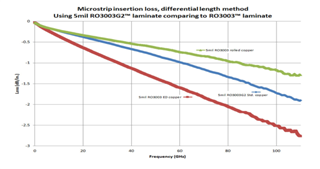
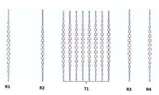
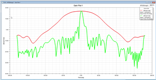
I am designing a high-gain antenna to replace the original one on the AWR1843Boost. Tx gain will be around 24dB and Rx gain around 17dB; thus it will have a very narrow beam to be utilized as stationary radar. SLL is around -20dB. Employing Ro3003G2. The simulations on the HFSS confirmed and satisfied our expectations. What could be your suggestions/warnings concerning the original pcb design and components.

Thank you.

Kind regards

  • Hi,

    The hardware team will review your request and get back to you tomorrow

    thank you
    Cesar

  • Hello Hasan,

         One of the concern with the high gain antenna is beam tilt across the frequency. If the significant beam tilt happens then you may miss the target. Small beam tilt is acceptable but need to analyze with the actual link budget to meet the desired detection target goals. 

    You may want to review the antenna gain and beam tilt across desired operating frequency band. It may not be big issue for narrow frequency bands, for example 76-77GHz. If you are planning to use broadband like 76-81GHz then you may have to look closely at this parameter. 

    Another aspect is you may have to match the antenna with the transmission lines. Antenna simulations should include transmission lines, any radiations & coupling from the transmission line will affect the antenna performance. At the edge of the Package is the 50Ohm reference plane for that transmission lines need to be connected and need to ensure good matching  i.e. S11 < -10dB for all the antenna ports.

    Package to PCB transition guideline is provided in the below app-note in section 2.1.2.

    https://www.ti.com/lit/an/spracg5/spracg5.pdf

    Along with the antenna, whole MIMO array simulation with the board routing need to be performed, to see any coupling effects and via, grounding effects that could alter the antenna performance. 

    Thanks and regards,

    CHETHAN KUMAR Y.B.

  • Hello Chethan,
     
    Thank you so much for the valuable inputs, much appreciated.  We will recheck our PCB design w.r.t. the points you have brought into attention. Regarding to the "beam tilt across operating frequency band" you pointed out, I am a little confused.  Attached are the characteristic curves of our Tx antenna design at this stage. We will employ it as 1 Tx and 4 Rx topology. The optimum frequencies of Tx and Rx arrays are matched at around 77.7GHz.  Rx arrays have gain around 17dB whereas Tx array appears to be around 24dB.  No beamforming needed. Long range stationary radar, we are interested in a beam width of only +/- 10 degrees.  Attached are the characteristic plots of the Tx array.  My inquiry: As seen in the Frequency as well as VSWR plots, the "optimum" frequency band is very narrow (i.e. gain drops considerably when the frequency moves off of 77.7GHz.)  Any possibility for beam tilting under these conditions and if there is what can we do to eliminate beam tilting?   
     
    Thanks and regards,
    Hasan Güz
     
  • Hello Hasan,

         Thank you for sharing the simulation results.

         Typically high gain antennas are used in longer distance and would be used for narrower frequency bandwidths, This is traded-off with the range resolution to meet the max distance, IF bandwidth, memory, MIPs etc computational goals. One would be using narrow RF frequency bandwidth typically 500MHz to 1GHz for longer distance. Hence, it should not be a big problem in your application.  Beam tilt is a typical problem in the series fed patch array PCB based Antenna designs for high gain antenna. You may want to re-run your link budget analysis by keeping desired frequency of operation, if the roll of of beam due to tilt is not acceptable, then you may want to reduce the gain and increase the beam with at the cost of reduced Tx/Rx gain.

    Another option is to consider beam steering capability offered by the Tx phase shifters. Device offers 6 Deg beam steering capability. This also warrants simulations to confirm grating and sidelobes are suppressed sufficiently. 

    Series fed patch antenna for higher gains also increases higher losses and over all decreased efficiency of the antenna. You may have to pay attention to this point as well, Lower substrate loss (like R03003 is one of lowest loss material even compared to Ro3003G2) will help in lowering the overall antenna loss. There are other consequences like peel strength, manufacturing constraints, bonding with other layers of substrate materials, drill, high temperature requirements etc also have to be carefully need to be weighted for the application requirements.  

    In your design, you have good match between 76 to 79GHz. That is good. And your best matching frequency is 77.7GHz, Due to limited etching tolerance from the PCB manufacture this frequency move up or down depending upon under etching or over etching of the traces and Antenna geometry. You may want to run simulation depending upon the min-max over etching and under etching tolerance limits of PCB manufacturer. If the frequency deviation is under your design limits then you are ok. Typically design is done such that Antenna/Transmission lines meets the design goals of PCB tolerance limits. 

    It may be wise to run the test after the fabrication to find out what would be optimum frequency at which best matching is obtained and design your chirps at those frequencies. 

    Thanks and regards,

    CHETHAN KUMAR Y.B.

  • Hello Chethan,

    Once again our gratitude for the insightful inputs; they were some genuine assistance for our design job. I would like to  hear your further comments based on our not-so-conventional topology.

    Being aware of resolution loss at high-gain long-range designs, we opted for a typical sparse array topology employing four independent 16-element Rx arrays and a single 8 x 16 element Tx array, all series fed. Our estimations  playing with inter-array distances indicated that a resolution about 1 degree or less (hopefully) would be possible. This has to be checked in the lab first then in the field (after integration to the 1843Boost circuit.)  Here is the topology we work on:

    (It might not look convenient for the feedlines on a single pcb plane while employing 1843 however we devised a way to  "feed" the T1 properly.)

    We still are in the designing phase, so your suggestions/inputs would help us a lot in proceeding on the right path toward the goal.

    Thanks and regards,

    Hasan

    P.S. About two months ago we applied to Rogers for rolled-copper 3003, however they suggested we base our designs on Ro3003G2 instead, saying rolled-copper 3003 can only be possible for very large amounts whereas G2 could be supplied readily most of the time. It was at first a little disappointing however our repeated design attempts assured us that all those arrays you see above have delivered better performance curves with 3003G2 than those we obtained with 3003.  

  • Hasan,

        Thank you for sharing the antenna structure. This structure is not uncommon and published in literature in many places. Below are some example  published in IEEE.  

    IEEE Xplore Full-Text PDF:

    IEEE Xplore Full-Text PDF:

    Conventional lamda/2 spaced virtual array would limit going into higher angular resolution, one has to explore other higher angular topology such as sparse array /MUSIC algorithms with some trade-offs. In sparse array topology one need to explore grating lobes/spectral leakage emanating due to gaps in the virtual array as compared to linear arrays. This would be limiting the dynamic range of angle estimation. Are you planning to use other Tx2 and Tx3 also to maximize the number of virtual antenna pairs?

    For further improving angular resolution, one could explore multichip cascaded solution in AWR2243 kind of product, But it would be more complex than single chip solution.   

    Yes, It's not clear from the picture for the feedlines, But care must be taken to minimize the transition losses and well matched to antenna ports.

    R03003G2 is relatively newer product introduced by Rogers in recent times, hence there may not be issue for the samples for proto developments, Where as R03003 has been existed in the market from many decades running high volume for most of the mmWave Automotive sensors. It may be challenging to acquire sample proto types, But one of the lowest losses material in the industry today. 

    Thanks and regards,

    CHETHAN KUMAR Y.B.

  • Hello Chethan,
     
    Just a final inquiry: Please note the gain curve below: Is this the "Beam Tilting" you warned about?
     
    Thank you.
  • Hello Hasan,

         This appears to be simulation done for the Rx antenna at 77GHz for Azimuth and Elevation cuts. You may wan to look at all the Antenna pairs. 

    If you are operating chirps from 77-78GHz or 77 -79GHz then you may want to review the whole frequency band for the antenna radiation pattern at say 500Mhz interval, and review antenna gain at the desired field of view and review does it meets the link budget requirement or not.

    Thanks and regards,

    CHETHAN KUMAR Y.B.

  • Once again, thank you so much, Sir.

    For those who are following this post I would like to add some information:

    - Rogers Corp have advised us in the meantime that  "we do not recommend RO3003 with Rolled Copper in automotive 77 GHz designs any longer.

    It is true that, theoretically speaking, Rolled copper gives the best insertion loss.

    On the other hand our practical experience shows there are manufacturing challenges with this kind of solution.


    One is that the thinning (i.e. plating down) and etching process for rolled copper at the PCB Manufacturers are not as consistent as ED copper. There are other more technical reasons related to manufacturing.


    This is why we developed and introduced to the market RO3003G2 that comes with very low profile ED copper. This is the perfect compromise between ease of manufacture, electrical performance and cost."


    - Regarding to Sparse Array Topology:  It is employed for High Angular Resolution,

     in our case aimed to be less than 1 degree.  It has nothing to do with the inter-element distances but with the inter-array distances that are determined by Genetic Algorithm.  For example the distance between R1 and R4 is 17 lambda-zero. Each array in this topology is located at some certain distances relative to each other calculated by Genetic Algorithm. For those interested I might suggest  D. Whitley; DOI: 10.1007/BF00175354 .


    Kind regards,


    Hasan

  • Hasan,

         Thank you for sharing feedback from the Rogers, Yes there are manufacturability challenges for the RO3003, Hence with the some performance trade-offs RO3003G2 is introduced.

    As I mentioned before which need to be dealt with, for avoiding the thinning process, typically thin 0.5Oz base copper is used and minimalistic plating process need to be adhered to avoid thinning process. In the current design two types of vias are used L1-L2 and PTH, these requires plating process. If there are different types of vias used this will warrant a additional plating process and increases the thickness of the top cu, then thinning process need to be employed. This will create uneven copper surface this is undesired for the transmission line and Antenna arrays, If it's not done properly especially for the large panels and also it degrades the surface roughness. Some PCB manufacturer use scrubbing process to thin down this is even worse, which causes even higher surface roughness causing more insertion loss. All these aspects need to be carefully to be discussed with PCB manufacturer. Hence one need to go with the PCB manufacture who has handled and perfected the art of manufacturing process for these material otherwise there would be considerable learning process to handle this material.

    Thank you for sharing the Genetic Algorithm used for getting Higher angular resolution.. This seem to unconventional but looks like promising. We don't have experience to comment on this. Our best wishes for your success on this project. 

    Thanks and regards,

    CHETHAN KUMAR Y.B.

  • Hi Chethan,
    We have received the inputs we needed and you may close this thread/post.
    Thanks and regards,
    Hasan Guz
  • Hello Hasan,

       Thanks for your confirmation. And once again best wishes for your success on this project. 

    Thanks and best regards,

    CHETHAN KUMAR Y.B.