This thread has been locked.

If you have a related question, please click the "Ask a related question" button in the top right corner. The newly created question will be automatically linked to this question.

IWR1443BOOST: Data conversion and integration

Part Number: IWR1443BOOST
Other Parts Discussed in Thread: IWR1443, DCA1000EVM

Dear Engineer,

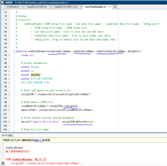
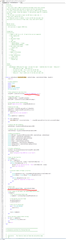
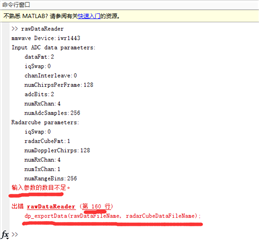
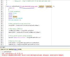
I'll start with a brief explanation of my situation: I'm using IWR1443BOOST+DCA1000EVN to get the raw data, and I can already generate the raw data store file adc_data.bin. I will describe my problem system once again, hoping to get a good solution.

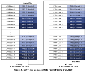
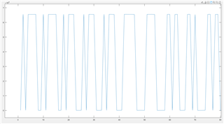
First of all, the first requirement is: I want to read the raw data dac_data.bin file correctly and convert them to. Mat file format. And I want to be able to get the raw data correctly mapped into the corresponding waveform.

Secondly, after meeting the first requirement, because I set the mode of infinite transmission of millimeter-wave, the amount of original data obtained at one time was relatively large, far exceeding the capacity of 1G, thus generating a series of data storage files such as ADC_data_0. Bin, ADC_data_1. I want to be able to read these files in the correct order and plot them as a continuous waveform.

Thanks.

Regards,

  • HI, there:

    In the mmwave studio, you can find a MATLAB script at C:\ti\mmwave_studio_02_01_01_00\mmWaveStudio\MatlabExamples\singlechip_raw_data_reader_example\

    This script should allow you to parse the data into the frame format, and it should also process through multiple files.  Please give a try and let me know. 

    Best,

    Zigang

  • HI,Zigang:

    Thank you for your reply. I will try this script and consult you again if I encounter any problems.

    Thans.

  • Dear Zigang,

    I do not have a deep understanding of the code of this MATLAB script. What are the parameters marked in the figure? How do I change the code?

    Thank you very much!

  • HI, Kelong:

    Please go through the readme.txt file to find the answer.  

    Best,

    Zigang

  • Dear Zigang,

    I have read readme.txt and exported the 1443.setup.json and 1443.mmwave.json files from MMWave Studio. But there are still some things I don't understand about these functions in the MATLAB script. I just made the changes in line 96 as shown in the first image and ran them as shown in the second image. I will send you setup.json and mmwave.json files and hope you can guide me how to modify these codes and functions. Thank you very much!

    8171.setup.json.txt
    {
      "createdByVersion": "2.1.0",
      "createdOn": "2021-10-26T16:01:40.3753322+08:00",
      "configUsed": "E:\\adc_data\\1443.mmwave.json",
      "captureHardware": "DCA1000",
      "DCA1000Config": {
        "dataLoggingMode": "raw",
        "dataTransferMode": "LVDSCapture",
        "dataCaptureMode": "ethernetStream",
        "packetSequenceEnable": 1,
        "packetDelay_us": 25
      },
      "mmWaveDevice": "iwr1443",
      "operatingFreq": 77,
      "mmWaveDeviceConfig": {
        "RS232COMPort": "COM15",
        "RS232BaudRate": "115200",
        "radarSSFirmware": "C:\\ti\\mmwave_studio_02_01_01_00\\rf_eval_firmware\\radarss\\xwr12xx_xwr14xx_radarss.bin",
        "masterSSFirmware": "C:\\ti\\mmwave_studio_02_01_01_00\\rf_eval_firmware\\masterss\\xwr12xx_xwr14xx_masterss.bin"
      },
      "capturedFiles": {
        "numFilesCollected": 1,
        "fileBasePath": "E:\\adc_data",
        "files": [
          {
            "rawFileName": "adc_data_Raw_0.bin",
            "processedFileName": "adc_data.bin",
            "processedFileSummary": {
              "numZeroFillBytes": 0
            }
          }
        ]
      }
    }

    1072.mmwave.json.txt
    {
      "configGenerator": {
        "createdBy": "mmWaveStudio",
        "createdOn": "2021-10-26T15:41:31.7392877+08:00",
        "isConfigIntermediate": 1
      },
      "currentVersion": {
        "jsonCfgVersion": {
          "major": 0,
          "minor": 4,
          "patch": 0
        },
        "DFPVersion": {
          "major": 1,
          "minor": 2,
          "patch": 0
        },
        "SDKVersion": {
          "major": 3,
          "minor": 0,
          "patch": 0
        },
        "mmwavelinkVersion": {
          "major": 1,
          "minor": 2,
          "patch": 0
        }
      },
      "lastBackwardCompatibleVersion": {
        "DFPVersion": {
          "major": 1,
          "minor": 1,
          "patch": 0
        },
        "SDKVersion": {
          "major": 2,
          "minor": 0,
          "patch": 0
        },
        "mmwavelinkVersion": {
          "major": 1,
          "minor": 1,
          "patch": 0
        }
      },
      "regulatoryRestrictions": {
        "frequencyRangeBegin_GHz": 77,
        "frequencyRangeEnd_GHz": 81,
        "maxBandwidthAllowed_MHz": 4000,
        "maxTransmitPowerAllowed_dBm": 12
      },
      "systemConfig": {
        "summary": "This is a comments field not passed to device",
        "sceneParameters": {
          "ambientTemperature_degC": 20,
          "maxDetectableRange_m": 10,
          "rangeResolution_cm": 5,
          "maxVelocity_kmph": 26,
          "velocityResolution_kmph": 2,
          "measurementRate": 10,
          "typicalDetectedObjectRCS": 1
        }
      },
      "mmWaveDevices": [
        {
          "mmWaveDeviceId": 0,
          "rfConfig": {
            "waveformType": "legacyFrameChirp",
            "MIMOScheme": "TDM",
            "rlCalibrationDataFile": "",
            "rlChanCfg_t": {
              "rxChannelEn": "0xF",
              "txChannelEn": "0x7",
              "cascading": 0,
              "cascadingPinoutCfg": "0x0"
            },
            "rlAdcOutCfg_t": {
              "fmt": {
                "b2AdcBits": 2,
                "b8FullScaleReducFctr": 0,
                "b2AdcOutFmt": 2
              }
            },
            "rlLowPowerModeCfg_t": {
              "lpAdcMode": 0
            },
            "rlProfiles": [
              {
                "rlProfileCfg_t": {
                  "profileId": 0,
                  "pfVcoSelect": "0x0",
                  "pfCalLutUpdate": "0x0",
                  "startFreqConst_GHz": 77.0,
                  "idleTimeConst_usec": 100.0,
                  "adcStartTimeConst_usec": 6.0,
                  "rampEndTime_usec": 60.0,
                  "txOutPowerBackoffCode": "0x0",
                  "txPhaseShifter": "0x0",
                  "freqSlopeConst_MHz_usec": 29.982000350952148,
                  "txStartTime_usec": 0.0,
                  "numAdcSamples": 256,
                  "digOutSampleRate": 10000,
                  "hpfCornerFreq1": 0,
                  "hpfCornerFreq2": 0,
                  "rxGain_dB": "0x1E"
                }
              }
            ],
            "rlChirps": [
              {
                "rlChirpCfg_t": {
                  "chirpStartIdx": 0,
                  "chirpEndIdx": 0,
                  "profileId": 0,
                  "startFreqVar_MHz": 0.0,
                  "freqSlopeVar_KHz_usec": 0.0,
                  "idleTimeVar_usec": 0.0,
                  "adcStartTimeVar_usec": 0.0,
                  "txEnable": "0x1"
                }
              }
            ],
            "rlFrameCfg_t": {
              "chirpEndIdx": 0,
              "chirpStartIdx": 0,
              "numLoops": 128,
              "numFrames": 0,
              "framePeriodicity_msec": 40.0,
              "triggerSelect": 1,
              "numDummyChirpsAtEnd": 0,
              "frameTriggerDelay": 0.0
            },
            "rlBpmChirps": [],
            "rlRfPhaseShiftCfgs": [],
            "rlRfProgFiltConfs": [],
            "rlLoopbackBursts": [],
            "rlDynChirpCfgs": [],
            "rlDynPerChirpPhShftCfgs": []
          },
          "rawDataCaptureConfig": {
            "rlDevDataFmtCfg_t": {
              "iqSwapSel": 0,
              "chInterleave": 0
            },
            "rlDevDataPathCfg_t": {
              "intfSel": 1,
              "transferFmtPkt0": "0x1",
              "transferFmtPkt1": "0x0",
              "cqConfig": 2,
              "cq0TransSize": 132,
              "cq1TransSize": 132,
              "cq2TransSize": 72
            },
            "rlDevLaneEnable_t": {
              "laneEn": "0xF"
            },
            "rlDevDataPathClkCfg_t": {
              "laneClkCfg": 1,
              "dataRate_Mbps": 600
            },
            "rlDevLvdsLaneCfg_t": {
              "laneFmtMap": 0,
              "laneParamCfg": "0x1"
            }
          },
          "monitoringConfig": {
          }
        }
      ],
      "processingChainConfig": {
        "detectionChain": {
          "name": "TI_GenericChain",
          "detectionLoss": 1,
          "systemLoss": 1,
          "implementationMargin": 2,
          "detectionSNR": 12,
          "theoreticalRxAntennaGain": 9,
          "theoreticalTxAntennaGain": 9
        }
      }
    }
    

  • HI, 

    You do not need to change the MATLAB script.   All you need to do is to pass the xxxx.setup.json file name through the MATLAB function call as mentioned in the readme.txt.  

    rawDataReader('C:\jsonScript\awr14\awr14xx.setup.json','adcData', 'radarCube', 0)

    All important is the first parameter xxx.setup.json file.  It contains the information to find mmwave.json file and the raw data file. 

    Best,

    Zigang

  • Dear Zigang,

    Thank you for your reply. Following readme.tet, my code calls the function as shown in the figure. I only modified line 85 and still get an error. Why? What can I do to run this script correctly?

  • HI, Zeng:

    Please do not change the script, instead  in the MATALB command window, you should typing:

    >>dbstop if error

    >>rawDataReader('E:\adc_data\1443.setup.json','adcData', 'radarCube', 0)

    Please use the original script when calling the above function. The first command will allow you to check all the intermediate value when anything goes wrong.  These are all MATLAB fundamentals.  

    Best,

    Zigang

  • Dear Zigang,

    Thank you very much for your reply. I got 'radarCube.mat' file and 'rawdata.mat' file belonging to raw data 'adc_data.bin' file correctly through rawDatareader.m. As shown in the picture below.

    I have a few more questions which I would like answered:

    Firstly, I want to know the format of the data stored in these two '**.mat' files. I saw the description in the page7-8 of 'Mmwave Radar Device ADC Raw Data Capture'  that the Data collected using IWR1443 with DCA1000 is captured over 4 LVDS Lanes and stored in an interlaced.bin file, as shown below. But I would like to know the data format of 'radarCube.mat' and 'rawdata.mat' files obtained by rawDatareader.m.

    Second, on the basis of the first point, I want to know how to draw the data in 'radarCube.mat' and 'rawdata.mat' files as waveform diagrams,and I want to know the vibration amplitude curve of the object tested with IWR1443BOOST over time.

    Third, I set the 'infinite frame mode' in MMWave Studio and generated multiple data storage files such as ADC_data_0.bin, ADC_data_1, etc. Can rawDatareader. m convert data from multiple rawdata.bin files to consecutive data from a '**.mat' file in the correct order? How do you get there?

    Thank you very much.

  • You can do:

    1) Source code rawDataReader.m line 211-221 give the information about what is the structure saved in rawdata.mat, it is a structure that contains both parameters and the rawADCData.  You can load this file as follows to 

    >> load rawdata.mat

    2) adcRawData.data{frameID} contains the raw ADC data for a certain frame.  It is 3-dimensional array, and the definition is defined in source code rawDataReader.m line 395-399. 

    % -----------------------------------------------------------------------
    % Description: This function reshape raw binary data based on capture
    % configuration, generates data in cell of
    % [number of chirps, number of RX channels, number of ADC samples]

    3) The radarCube.mat is similar, you can load it to check this structure, and data format is the same as above.

    4) To draw data, you can use MATLAB function, like "plot", for example, you can plot raw ADC data for the first frame, first chirp and first antenna as follows:

    figure; plot(adcRawData.data{1}(:, 1, 1))

    5) rawDataReader.m should already support multiple data storage.   The number of files should be defined in the setup json file. 

    numBinFiles = length(setupJSON.capturedFiles.files);

    Best,

    Zigang

  • Dear Zigang,

    1)I use "figure; plot (adcrawdata.data {1}(:,1,1))" and get the following figure. what the x and y axes in this picture refer to?

    2)I have a question that I have not been able to understand, that is, what information is captured by ADC1000EVM? What information does a stored binary contain? 

    I've been doing a lot of research on the Internet(I am new to the radio field, so the information may not be accurate, thank you for correcting me if there is any mistake). My understanding is that a TI board emits a signal called a "chirp" whose frequency varies linearly with time. A set of chirps forms a "frame". The time of receiving reflected signals from targets at different distances is different.

    So, what kind of information does TI board store? Is it the time it takes for the signal to go from the transmitter to the target to the receiver or something else? I have looked it up for several days. It is a pity that I could not get more detailed information. I am looking forward to getting an answer from you.

  • 3)I need to use IWR1443BOOST+DCA1000EVM for an experiment: aim the board at the chest of a person at an interval of about 1 meter for continuous observation for 1 hour, and capture the data within 1 hour through DCA1000EVM.

    I want to see how the phase of the signal changes over time over the course of an hour, and the phase changes are due to the breathing and the heartbeat.

    How do I get what I want with the data captured by DCA1000EVM? What should be done to DCA1000EVM data?

  • 1) The raw ADC data should be ADC data and is complex value, including real and imaginary.  Sorry, my example was wrong, since the three dimensional array is [number of chirps, number of RX channels, number of ADC samples], so to plot the ADC sample of the first frame, first chirp and first antenna, you should look at:   figure; plot(abs(adcRawData.data{1}(1, 1, :))).  Can you check whether the signal are complex values?

    2) ADC data is the ADC output of the received chain.  You can go through the device datasheet to understand the RX chain. 

    3) To develop new vital sign demo, you can start with the vital sign demo and read through the document located at:  dev.ti.com/.../node

    Best,

    Zigang

  • dear zigang

    Can you tell me what the stored complex values mean?

  • The ADC data has I sample (real) and Q sample (imaginary), the data should be constructed as  I_sample + 1j* Q_sample before saved in as .mat file.

    Best,

    Zigang

  • dear zigang,

    I found the 3d matrix data for each frame [chirp, antenna, sample] in radarCube.data, 128*4*256. Each sample is a complex value.

    Here, I have a question. In my opinion, the radar receiving antenna will receive multiple different reflected signals at one time, and these reflected signals have different frequencies. Why is the data stored only a complex value?

    And where is the time information stored? How do I get dynamic time information? Because the data storage method in radarCube. Data is to store the 128*4*256 3D matrix [chirp, antenna, sample] of each frame in a cell. For example, if I want to know the distance change of a moving target over time, How do I get what I want from such a complex number?

    Finally, is it convenient to ask a personal question? What are your usual working hours? Local time or US time. Due to the distance between time zones, I cannot timely issue new questions or reply to your reply. If you could tell me your working hours, maybe it would be more convenient for us to communicate without sending or replying messages for more than ten hours each time?

    Thank you very much!

  • Hi, Zeng:

    You can understand the fundamentals of FCMW radar from the training https://training.ti.com/intro-mmwave-sensing-fmcw-radars-module-1-range-estimation?context=1128486-1139153-1128542.  These are the best training we have so far.  

    Since now you are able to parse the raw ADC data and I will close this ticket.   You can submit new ticket for your new questions.  

    Best,

    Zigang