This thread has been locked.

If you have a related question, please click the "Ask a related question" button in the top right corner. The newly created question will be automatically linked to this question.

LDC0851: ABOUT LDC coil design

Part Number: LDC0851
Other Parts Discussed in Thread: , LDCCOILEVM

Thank you very much for your help.

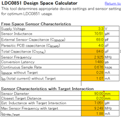
I would like to design a sensing coil using LDC0851, with the size of the object to be detected (dout: 90.0 mm: 90φ), and the detection distance D is less than 0.2 mm.
I would like to design a sensing coil with a detection distance D of less than 0.2mm using LDC0851.
Please let me know the following.

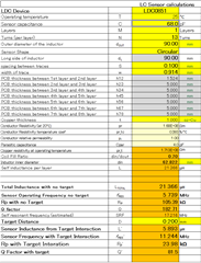
For your information, I will use LDC_Inductance_calculator to support the coil design.
is used to support the coil design.

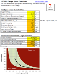
1) Sensor Inductance from target interaction, which is calculated when 0.2mm is entered in "Target_Distance".
Sensor Inductance from target interaction, Sensor frequency with target interaction, and
Sensor frequency with target interaction, Rp with target interaction
(2) Is it correct to think that Sensor Inductance from target interaction, Sensor frequency with target interaction, and Rp with target interaction are the parameters to realize the detection distance?

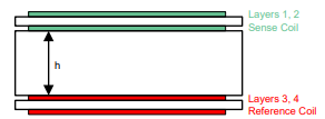
(2) Regarding the number of substrate layers.
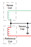
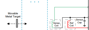
In LDC0851, reference coil (LREF) and sensor coil (LSENSE) are used.
In this case, the number of substrate layers is 2.
In this case, I think the number of substrate layers should be 2.

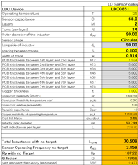
(3) Coil design parameters
In order to determine the detection distance, the following parameters are required.
Sensor_capacitance, Layers
Layers, Turns, and
Turns, and
Dout (Outer_diameter), Spacing between traces
Spacing between traces
width of trace
However, if I want to sense only the short distance of less than 0.2mm without changing Dout, which parameters should I use?
However, which parameter should be used as the standard to sense only the short distance of less than 0.2mm without changing Dout?

Thank you very much for your help.

  • Hello, 

    To clarify, is 0.2mm you desired switching distance is it is a smaller distance? What is your maximum and minimum distances in this application? 

    For the LDC0851, I would take the parameters without target interaction and plug them into the LDC0851_calc tab of the spreadsheet. Doing so, you can have a better view of the operation of the sensor: 

    In regards to the number of layers, this is specific to each coil (ref and sense). So if you have a 2 layer board and are using a stacked design, each coil will only exist on one layer. If you have a 4 layer board and a stacked design, then it will be 2 layers per coil. 

    For changing the coil parameters for a 0.2mm distance the concern is hitting the current limitations at the shortest distance. You can change the turns, trace width, and trace spacing to adjust the inductance and Rp of the sensor so that it isn't a concern. 

    The sensor diameter is a big factor in the sensing distance. You don't need to have your sensor diameter the same as your target. For large targets, you can use a smaller sensor as long as the sensing distance is shorter than the sensor diameter. One concern in this though is having motion that isn't completely in the z axis of the sensor. If the target tilts a bit, then the sensor may not properly catch the change in the target. You can use multiple small sensors if needed to alleviate this. This isn't a requirement, just an alternative suggestion. 

    Best Regards, 

    Justin Beigel

  • Thank you for your help.

    I have received your answer, but there is still something I don't understand, so please elaborate.

    First.
    1. Switching distance.
    0.2 mm is the switching distance, and the maximum distance is 0.2 mm. The minimum is 0.05mm, which is as close to zero as possible.

    2.How to use the LDC calculation sheet
    "For the LDC0851, you need to get the parameters without any interaction with the target, and then click on the LDC0851_CLAC tab in the spreadsheet.
    LDC0851_CLAC tab in the spreadsheet." Thank you for your help.

    Specifically, enter C, M, N, dout, dL, S, and W, get Ltotal, and enter it in sensor_inductanse of LDC0851_calc and
    Ltotal is then input to sensor_inductanse in LDC0851_calc and Closest Target_Distanse to obtain
    Est Inductance with Target Interaction, Max Sensor Frequency with target, and
    Max Sensor Frequency with target,
    In the Spiral_induction_Design screen again, refer to
    Is the procedure to adjust C,M,N,dout,dL,S,W to get the value of EST inductance with target Interaction?

    3.About PCB coil (LDC_coil_EVM)
    From the text you provided, I interpreted that it is possible to use both reference and sensor coils on a single multilayer PCB, but each coil of LDC_coilEVM is different from each other.
    However, I heard that each coil of LDC_coilEVM can only be used as either a reference coil or a sensor coil, and that two sets of coil EVMs are required when connecting to LDC0851EVM. Is this wrong?

    4. Experiments using the LDC coil EVMs
    I want to make sure that the switching distance is as small as possible. How should I arrange the PCB of the reference coil and the PCB of the sensor coil? How can I place the two PCB coils on top of each other?
    Please let me know how to place the two PCB coils on top of each other without difficulty.

    Thank you very much.

  • Hello, 

    Is the procedure to adjust C,M,N,dout,dL,S,W to get the value of EST inductance with target Interaction?

    Yes. For a circular inductor, you won't change dL, but everything else can be changed to adjust the inductance. 

    However, I heard that each coil of LDC_coilEVM can only be used as either a reference coil or a sensor coil, and that two sets of coil EVMs are required when connecting to LDC0851EVM. Is this wrong?

    This is correct. However, the LDC0851 can be used with either a stacked coil design or a side by side design: 

    Side by side:

    Stacked: 

    What is the motion of your target? Is it the same as above (in line with the sensor) or is it perpendicular to the sensor coils? 

    Also, here is an image of the stacked coil design from a PCB perspective: 

    If you are using the LDCCOILEVM sensors, then you can add an insulator between them to separate the two coils. 

    Best Regards, 

    Justin Beigel