This thread has been locked.

If you have a related question, please click the "Ask a related question" button in the top right corner. The newly created question will be automatically linked to this question.

DRV5023: What parts to use to set up a sensor using DRV5023AJQLPGM to detect the charge

Part Number: DRV5023

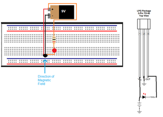
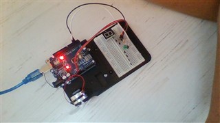
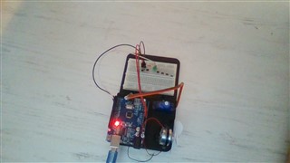
Hey everyone, I hope your day is going well. I have a quick question on how to set up my sensor (part number DRV5023AJQLPGM), as I am a novice in this field of electronics and sensors. I am trying to use this sensor, which was recommended to me by a colleague, to detect particles (which I believe this will be able to do according to my calculations), but i am unsure what else I need to do to set this up. A so called breadboard? Some wires? If so, what type? A light so when the sensor goes off I will be able to tell that it did? I am very new to all of this and need advice. Thank you so much for your time, and a response as soon as possible would be very very much appreciated. 

  • Hello --,

    Thanks for considering to use Texas Instruments.  What kind of particles are you detecting?  If you have a strong enough magnetic stimulus, you can try the following setup.  I think 22 AWG wire might work in a breadboard for you.  The diagram below shows the TO-92 package option.  When the magnetic stimulus is strong enough the out put pin pulls low which allows the Red LED to turn on.  I chose a 1k resistor, but you could use some other value.

  • Thank you so much for your response sir! I am trying to detect virtual particles from UV photons by detecting their charge. Ok so should I also purchase a breadboard and some 22 AWG wore which I think I can get from TI? And then once I do just set it up like in the diagram? Thank you!!

  • Hello --,

    I have not heard of our devices being used for UV light or photon detection, perhaps a light sensor might be more appropriate for your application.  If you wish to proceed with our Hall-effect device, you can likely get a breadboard and wire off of amazon, digikey, mouser, or possibly alibaba.  The magnitude of your magnetic stimulus needs to be directed normal to the package as indicated in the figure below.

  • Okay I think this Hall effect sensor will work for my project. Will this breadboard be suitable for 50 sensors (https://www.digikey.com/en/products/detail/parallax-inc/700-00078/3523672) and is this 22 AWG wire okay (https://www.amazon.com/Arrozon-70-5FT-2Pin-Extension-Cable/dp/B0912KT2TN/ref=mp_s_a_1_2_sspa?dchild=1&keywords=22+awg+wire&qid=1635970679&sr=8-2-spons&psc=1&spLa=ZW5jcnlwdGVkUXVhbGlmaWVyPUEzU00yTFZYNU1KNE0xJmVuY3J5cHRlZElkPUEwOTMxNjMxMTdNSjBFQU9ZQTlVOCZlbmNyeXB0ZWRBZElkPUEwNzMyMDM5MzBBVTBGVzVRSlI4MyZ3aWRnZXROYW1lPXNwX3Bob25lX3NlYXJjaF9hdGYmYWN0aW9uPWNsaWNrUmVkaXJlY3QmZG9Ob3RMb2dDbGljaz10cnVl)? What other materials do I need? And how exactly would I set this up (if you could give a step by step that would be very much appreciated)? I’m sorry this probably seems very elementary to you but I am very new to all of this as I am only a teenager in middle school. Thank you once again sir.

  • Hello --,

    Glad to see you are interested in electronics at such an early age.  I unfortunately cannot give you that level of support.  However, I can point you to a site that might help you with understanding how to interact with a Hall Sensor and how it works.  Here is one such site.  I would recommend you look a little into using an arduino which that site uses.  Around the arduino there is a community of electronic enthusiasts you can learn from.

    Aside from that, I really think you should use a light sensor.  When it comes to UV light, I dont think TI has an appropriate product for that spectrum of light.  However, this sensor module on Digikey might be good.

    That bread board looks standard and I think it will work for you, but you may need more than 1 if you have 50 sensors, regardless of whether it is Hall-effect device or a light sensing device.  I think a wire kit like this might be better for you.  If you need longer wire, I suggest this.  Solid wire is easier to work with than stranded wire when working with a breadboard.  You probably should get some wire cutters too.

  • Ok that site you shared seems very helpful thank you that is exactly what I need to do build. I want to use the Hall effect sensors because I am not trying to detect the light itself, but rather the virtual particles that “pop” into existence by quantum fluctuation and the Heisenberg uncertainty principle.

  • Ok so would this (https://www.digikey.com/en/products/detail/kitronik-ltd/5313/9998805) have everything (Arduino, wires, breadboard, LEDs, resistor, etc.) that I need besides the DRV5023 sensors which I already have and some wire cutters which I have?

    If not, how are these (links are embedded)? I just want to make sure that they would work and are reliable.

    Wires

    Breadboard

    10k ohm resistor

    1k ohm resistor

    LED

    Anything else I'm missing?

  • Hello --,

    That looks like a good starter kit.  I would also recommend a 0.1ufF capacitor to go between ground and the supply.  However, that kit does come with an electrolytic which you probably could use.  I would just make sure you pay attention to the capacitor's polarity.

  • Hello again sir, I hope all is well. I have almost finished the setup for my detector, as shown below.

    First of all, is this setup ok (I'm still waiting on a 9V male clip and the plug to connect to the board)? I am using 10 uF and 0.1 uF capacitors, the sensor, a green LED, and connecting wires.

    Also, the code I am using is from the link you recommended, but how would I make set it up so that when the magnet is detected, a number will light up on the 7 segment display rather than an LED light up (having both would be nice as well.) and the display will keep track of the number of detections? I tried to research how to code this but I didn't get many good results, so I thought I'd ask you. Thank you for all your help, and have a great rest of your day.

  • Hello --,

    Actually you do not need the 9V battery.  Your Arduino board should have a 5V pin.  As your Arduino is already powered (I presume from your laptop or computer), I would just run a wire from the arduino board 5V pin to you your sensor VCC pin and your LED anode and I think your laptop supply should be able support the current. It looks like you might already be doing that.

    As for how your Hall-effect sensors are placed, I think those are fine.  However, it is a little difficult to see where all the pins of your various components go.  I think you would probably need to reorient your 7-segment.  You might not have adequate room to fit that and everything else on your board.

    Here is a link that covers working with a single 7 segment.

  • Ok thank you I didn't notice that. I set it up as shown in the picture, so hopefully that works. Also, I took out the segment display so I'd have more room for the sesnors, not all of which I've put in yet, since it's not a big deal since I can just see if the LED blinks. So is it okay if I put sensors going along every row in the bread board until the end +/- rows?

    Another issue is that when I try to run the code, I get an error message saying "serial port not selected." How can I fix this?

    Once again, thank you for all your help.

  • Hello --,

    For that issue, this video might help.  For further arduino issues, I would recommend going to an arduino forum if you cannot find a youtube video that covers how to fix your problem.  My knowledge on arduino is limited and I can only help you so much on that topic.

    However, I can fully support you on Hall-effect sensors and TI products if you have any further questions.

  • Ok thank you sir I'll do that. The video you sent was very helpful however it didn't work when I tried it and it said to close out of all applications and restart Windows, so I'll do that and then if that doesn't work then I'll head to an arduino forum. I also duplicated what I did on rows f-j and did it again on a-e, if you think that's a good idea. Thank you for all your help, and have a great Thanksgiving!

  • Your welcome.  You might also try using a alternate USB ports. I know I have had some ports in the past the were not reliable while others on my computer were. I think having two rows of Hall-effect sensors, one on f-j and one on a-3, is fine from an electrical connection standpoint.  Whether it is appropriately positioned for measuring your field, that I cannot say without further detail.

    Good luck! Happy Thanksgiving to you too!