Hi E2E,
We need your guidance in using the TUSS4440 Transformer drive ultrasonic sensor in our customer’s application. Here are the full details of the query:
I have a custom 4 layer board with tuss4440. How can I increase the echo signal while maintaining a low noise floor.
I am using a 40 khz closed top transducer. You can see the drive signal in blue and the Recieve signal in yellow.


I assume the output is DC and there is an offset from ground. When setting the threshold based on this waveform would it be 700mv?
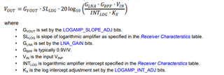
I notice in many of the waveforms in the presentation you are getting much more voltage than in my waveform. I think I have the slope and intercept set produce low output as i was trying to minimize the noise floor.
The object is a large sheet of plywood 1 meter away. I really need more echo signal as my maximum distance will be 2m.
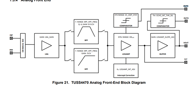
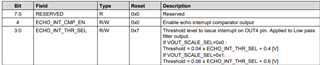
The out3 can be used to monitor the signal. Can you detail the process of using this signal to make an adjustment? Can you give a practical example? I am exploring all possible ways to optimize my circuit.
DEV_CTRL_2
'00000000' ; Map to 3.3 volts 15v/v
DEV_CTRL_3
'00000001'
VDRV_CTRL
'01000000'
BURST_PULSE
'00010000'
BPF_CONFIG_1
'00000000'
BPF_CONFIG_2
'00000000'
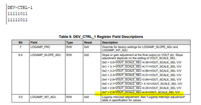
DEV_CTRL_1
'10000111'
ECHO_INT_CONFIG
'00011111'
ZC_CONFIG
'11010100'
XFMR_DRV_LIM
'00100011'
TOF_CONFIG
'01000010'

Thank you for the assistance.
Regards,
Carlo