This thread has been locked.

If you have a related question, please click the "Ask a related question" button in the top right corner. The newly created question will be automatically linked to this question.

IWR6843: board can not connect

Part Number: IWR6843
Other Parts Discussed in Thread: , MMWAVEICBOOST

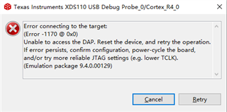
I use  IWR6843  to make a board. Because LP87524 is out of stock, I use LP87523 instead of it. Another chip is used as the 3.3V voltage regulator chip.I  have config the lp87523 through a MCU IIC.But I can not connect the board through JTAG or UART.

The following items have been determined,

(1)Each channel voltage is normal;

(2)The crystal work normally;

(3)The simulator work normally on IWR6843 EVM;

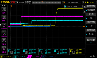
I test my board some pins voltage, sop0 = 3.29V, sop1 = 1.55V,sop2 = 1.55V, TMS = 2.586V,TDO = 3.29V,TDI = 2.584V,TCK = 0V;

and IWR6843 EVM board pins voltage, sop0 = 3.27V, sop1 = 1.2V,sop2 = 1.2V, TMS = 3.13V,TDO = 3.27V,TDI = 3.14V,TCK = 0V;

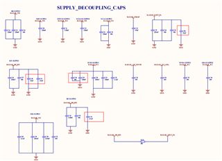
The attached picture is a schematics.

Can anyone answer?

Thank you.

Regards.

  • Hello

    Can you please help us understand what do you mean by board cannot connect?

    Is the device able to boot? 

    Was flash loading step tried?

    Thank you

    Vaibhav

  • Hi Vaibhav,

        We through XDS110 load program to the IWR6843. The CCS10.0 says it can't connect.

        I am not sure if IWR6843 starts normally.

        We have tried to load program to flash.But failed.

        Regards.

        Qiang

  • Hi Vaibhav,


        This is the tip of ccs10.0. We have tried to reset IWR6843, but no effect.

        The following figure shows the voltage measurement values of 4 channels.


        Regards.

        Qiang

  • Hi Vaibhav,

        Today,We continued to test my board. I find XDS 110 can connect IWR6843, but it can only connect to DSP, and cannot connect to ARM.

        I am wondering if this is the cause of poor soldering of IWR6843.

        Looking forward to your reply.

        Thank you.

        Best regards.

       Qiang

  • Hello

    Thank you for the update.  A few questions:

    What was changed to make the XD110 connect ?  

    Was it on same board or a different one ?

    Thank you,

    Vaibhav

  • Hi Vaibhav,

        Thanks for your reply.

       1.What was changed to make the XD110 connect ?  

             We just plugged in and unplugged the cable again.

       2. Was it on same board or a different one ?

             Yes, These are all made on the same board.But sometime, We can connect to IWR6843,  sometime wo can not connect to IWR6843.

       Best regards

       Qiang

  • Hello,

    Can you share the full schematic in PDF format?

    I don't see any pullup on warmreset. Can you confirm you have all of the required pullups as defined in the schematic checklist?

    https://www.ti.com/lit/zip/swrr161

    Regards,

    Adrian

  • Hi Adrian, 

        Sorry, I can not share the full schematic. But I can share the schematic related to IWR6843.


        The warmreset should not have a pullup.I need further confirmation.

        Best regards.

        Qiang

  • Hello,

    A pullup is required on warmreset otherwise the device will be stuck in a soft reset. Can you try soldering a resistor onto the warmreset pin to 3.3V and see if that resolves the issue?

    Regards,

    Adrian

  • Hi Adrian,

        Thank you. I will try it. 

         Regards.

         Qiang

  • Hi Adrian,

        We tried the method you said, but it still doesn't work. 

        When we run the code,CCS10.0 prompts to wait until BSS powerup is done.


        Regards.

        Qiang

  • Hello,

    Would it be possible to share the full schematic via email to maintain the privacy of your design? It is very typical for customers to allow us to internally review the full schematic design and this would make it a lot easier to identify the issue.

    Let me know if this would be possible and I will share my email with you.

    Regards,

    Adrian

  • Hi Adrian,

        I can share full schematic via email.Please tell me your email address.

        Thank you.

        Regards.

        Qiang

  • Hi Vaibhav and Adrian,

        In recent days, we have made some progress.But I must apologize to you. Due to our carelessness, the connecting wires of sop2 and sop1 were connected reversely.Now, we can download program through UART.

        After further inspection, we found that program debugging can be performed after SOP0, SOP1, and SOP2 are set to 0,0,1.

        Previously, we set 1, 0, 1. This confignation can be used on IWR6843ISK. We do not know why. Because 0,0,1 is run mode, 1, 0, 1 is debug mode.

        Now, the program is still running abnormally,stuck in some places.We need to check further.

        But there is another thing that needs your help. It's about IWR6843ISK and MMWaveICBOOST. We have encountered the following problems.

        (1) Few days ago, when we test MMWaveICBOOST voltage, there was a situation where IWR6843 ISK was no longer powered on through HD CONNECTOR(60 pin). We found IWR6843 ISK can get 5V, but PMIC did not work. However,after IWR6843ISK and MMWaveICBOOST are separated,when IWR6843ISK is only powered by microUSB, the IWR6843 and PMIC can work.

        (2) When IWR6843 ISK is powered by microUSB alone, we toggle the keys to test the board voltage. But IWR6843 ISK seems to have a short circuit, the PMIC does not work, and the current reaches 1A.

        How can we repair IWR6843 ISK and MMWaveICBOOST?

        Thank you.

        Regards.

        Qiang

  • Hi Vaibhav,

        We have another problem and need your help.

        During the previous test,  Vital Signs demo can run normally on IWR6843ISK.But Vital Signs demo runs abnormally on our board. We get some information through  UART debugging tool.

        We found that the configuration of chripCfg(0 0 0 0 0 0 0 1) is abnormal, prompting "Not found". The configuration of calibDcRangeSig and sensorStart are also abnormal. Since IWR6843ISK can’t work anymore, we can’t compare and analyze.

        What is the reason for this? How should we debug?

        Thank you.

        Regards.

        Qiang

  • Hi Adrian and Vaibhav,

        After adjusting the program, the board can run normally.Thanks for your help.

        Regards.

        Qiang