Other Parts Discussed in Thread: AWR2243, DCA1000EVM, AWR1243, AWR1843
Hello I have a problem with using AWR2243 + DCA 1000 as I have my own application development .
in mmwave_dfp_02_02_03_01 as I use mmwaveconfig.txt from this directory mmwave_dfp_02_02_03_01\ti\example\mmWaveLink_SingleChip_Example.
and I change mmwaveconfig.txt like this:
#
#For detailed view of mmWave Radar configuration structure
#please refer
#ti\control\mmwavelink\docs\doxygen\html\index.html
#
#
#cascade mode enable
#
cascade_enable=0;
#END
#
#power on master arguments, please modify if needed.
#rlClientCbs_t: crcType 0:16Bit/1:32Bit/2:64Bit, ackTimeout
#
crcType=0;
ackTimeout=1000;
#END
#
#channel config parameters, please modify if needed.
#rlChanCfg_t
#
channelTx=7;
channelRx=15;
cascading=0;
#END
#
#ADC out config parameters, please modify if needed.
#rlAdcOutCfg_t
# adcFormat= {0(Real), 1(Complex), 2(Complex with Image band), 3(Pseudo Real)}
# adcbits = {0(12 Bits), 1(14 Bits), 2(16 Bits)}
#
adcBits=2;
adcFormat=2;
#END
#
#DATA format config parameters, please modify if needed.
#rlDevDataFmtCfg_t
# adcBitsD = {0(12 Bits), 1(14 Bits), 2(16 Bits)}
# adcFmt = {0(Real), 1(Complex), 2(Complex with Image band), 3(Pseudo Real)}
# iqSwapSel = {0 (I sample first), 1 (Q sample first)}
# chInterleave={0 (interleaved), 1 (non interleaved)}
#
rxChanEn=15;
adcBitsD=2;
adcFmt=1;
iqSwapSel=0;
chInterleave=0;
#END
#
#Low power config Paramters, please modify if needed.
#rlLowPowerModeCfg_t
# lpAdcMode = {0 (regular ADC mode), 1 (low power ADC mode)}
#
anaCfg=0;
lpAdcMode=0;
#END
#
#Data Path config parameters, please modify if needed
#rlDevDataPathCfg_t
# intfSel = {0 (CSI2), 1 (LVDS), 2 (SPI)}
# transferFmtPkt0 = {1 (ADC_DATA_ONLY), 6 (CP_ADC_DATA), 9 (ADC_CP_DATA), 54 (CP_ADC_CQ_DATA), b7:6= 00 (Virtual channel number 0), 01 (Virtual channel number 1), 10 (Virtual channel number 2), 11 (Virtual channel number 0)}
# transferFmtPkt1 = {0 (Suppress Packet 1), 14 (CP_CQ_DATA), 11 (CQ_CP_DATA), b7:6= 00 (Virtual channel number 0), 01 (Virtual channel number 1), 10 (Virtual channel number 2), 11 (Virtual channel number 0)}
# cqConfig = {0 (12 bit), 1 (14 bit), 2 (16 bit)}
# cq0TransSize = 32-128
#
intfSel=1;
transferFmtPkt0=1;
transferFmtPkt1=0;
cqConfig=2;
cq0TransSize=132;
cq1TransSize=132;
cq2TransSize=72;
#END
#
#LVDS clock config parameters, please modify if needed
#rlDevDataPathClkCfg_t
# laneClk = {0 (SDR), 1 (DDR)}
# dataRate = {0 (900 Mbps in DDR), 1 (600 Mbps in DDR), 2 (450 Mbps in SDR, DDR), 3 (400 Mbps in DDR), 4 (300 Mbps in SDR, DDR), 5 (225 Mbps in DDR), 6 (150 Mbps in SDR, DDR)}
#
laneClk=1;
dataRate=1;
#END
#
#SET HSI clock parameters, please modify if needed.
#rlDevHsiClk_t
# hsiClk = {9 (600 Mbps in DDR), ...}
#
hsiClk=9
#END
#
#LANE config parameters, please modify if needed.
#rlDevLaneEnable_t
# laneEn = 0-15 indicating how many lanes are active
laneEn=15;
#END
#
#LVDS Lane Config parameters, please modify if needed.
#rlDevLvdsLaneCfg_t
# laneFmtMap = {0 (Rx0,Rx1,...), 1 (Rx3,Rx2,...)}
# laneParamCfg = {b0: (0(LSB first), 1(MSB first)), b1: (0(Packet End Pulse Disable), 1(enable)), b2: (0(CRC disabled), 1(CRC enabled))}
#
laneFmtMap=0;
laneParamCfg=1;
#END
#
#Profile config parameters, please modify if needed.
#rlProfileCfg_t
# startFreqConst = freq/(53.644 Hz), so if freq is ~77 Ghz, then startFreqConst = 1435388860
# idleTimeConst = (idle time) / (10 ns)
# freqSlopeConst = (slope KHz/us)/(48.279 KHz/us)
# txStartTime = (t)/(10 ns)
#
#
profileId=0;
startFreqConst=1435388860;
idleTimeConst=1000;
adcStartTimeConst=200;
rampEndTime=4000;
txOutPowerBackoffCode=0;
txPhaseShifter=0;
freqSlopeConst=630;
txStartTime=100;
numAdcSamples=256;
digOutSampleRate=10000;
hpfCornerFreq1=0;
hpfCornerFreq2=0;
rxGain=30;
#END
#
#Chirp #1 Configuration parameters, please modify if needed.
#rlChirpCfg_t
# txEnable = {b0 (ant0), b1 (ant1), b2 (ant2)}
#
chirpStartIdx=0;
chirpEndIdx=0;
profileIdCPCFG=0;
startFreqVar=0;
freqSlopeVar=0;
idleTimeVar=0;
adcStartTimeVar=0;
txEnable=1;
#END
#
#Frame configuration parameters, please modify if needed.
#rlFrameCfg_t
# triggerSelect = {1,2} for {SW,HW} triggers
# numAdcSamples = should be the same as the profile config.
# periodicity = t / (5 ns)
#
chirpStartIdxFCF=0;
chirpEndIdxFCF=0;
frameCount=0;
loopCount=32;
numFrames=0;
periodicity=6000000;
triggerDelay=0;
numAdcSamples=256;
triggerSelect=1;
#END
#
#Advance Frame configuration parameters, please modify if needed.
numOfSubFrames=4;
forceProfile=0;
numFrames=100;
loopBackCfg=0;
triggerSelect=1;
frameTrigDelay=0;
#end
#
#4th sub Frame configuration parameters, please modify if needed.
forceProfileIdx=0;
chirpStartIdxAF=0;
numOfChirps=1;
numLoops=8;
burstPeriodicity=5000000;
chirpStartIdxOffset=0;
numOfBurst=1;
numOfBurstLoops=1;
subFramePeriodicity=5000000;
numAdcSamplesAF=256
numChirpsInDataPacket=1
#end
#
#3rd sub Frame configuration parameters, please modify if needed.
forceProfileIdx=0;
chirpStartIdxAF=0;
numOfChirps=1;
numLoops=8;
burstPeriodicity=5000000;
chirpStartIdxOffset=0;
numOfBurst=1;
numOfBurstLoops=1;
subFramePeriodicity=5000000;
numAdcSamplesAF=256
numChirpsInDataPacket=1
#end
#
#2nd sub Frame configuration parameters, please modify if needed.
forceProfileIdx=0;
chirpStartIdxAF=0;
numOfChirps=1;
numLoops=8;
burstPeriodicity=5000000;
chirpStartIdxOffset=0;
numOfBurst=1;
numOfBurstLoops=1;
subFramePeriodicity=5000000;
numAdcSamplesAF=256
numChirpsInDataPacket=1
#end
#
#1st sub Frame configuration parameters, please modify if needed.
forceProfileIdx=0;
chirpStartIdxAF=0;
numOfChirps=1;
numLoops=8;
burstPeriodicity=5000000;
chirpStartIdxOffset=0;
numOfBurst=1;
numOfBurstLoops=1;
subFramePeriodicity=5000000;
numAdcSamplesAF=256
numChirpsInDataPacket=1
#end
#
#Continuous mode config parameters
#startFreqConst=1435384036;
#txOutPowerBackoffCode=0;
#txPhaseShifter=0;
#digOutSampleRate=10000;
#hpfCornerFreq1=0;
#hpfCornerFreq2=0;
contModeRxGain=30;
vcoSelect=2;
#end
#
#Dynamic Chirp Config parameters
chirpSegSel=0;
chirpNR1=167918592
chirpNR2=8388000
chirpNR3=262148080
#Temp Mon configuration parameters, please modify if needed.
AnaMon_enMask=402604031;
AnaMon_ldoVmonScEn=15;
#END
#
#Temp Mon configuration parameters, please modify if needed.
TempMon_reportMode=2;
TempMon_anaTempThreshMin=-40;
TempMon_anaTempThreshMax=135;
TempMon_digTempThreshMin=-40;
TempMon_digTempThreshMax=135;
TempMon_tempDiffThresh=30;
#END
#
#Rx Gain Phase Mon configuration parameters, please modify if needed.
RxGainPhaMon_profileIndx=0;
RxGainPhaMon_rfFreqBitMask=7;
RxGainPhaMon_reportMode=2;
RxGainPhaMon_txSel=0;
RxGainPhaMon_rxGainAbsThresh=500;
RxGainPhaMon_rxGainMismatchErrThresh=500;
RxGainPhaMon_rxGainFlatnessErrThresh=500;
RxGainPhaMon_rxGainPhaseMismatchErrThresh=18204;
RxGainPhaMon_rxGainMismatchOffsetVal=0;
RxGainPhaMon_rxGainPhaseMismatchOffsetVal=0;
#END
#
#Rx Noise Mon configuration parameters, please modify if needed.
RxNoiseMon_profileIndx=0;
RxNoiseMon_reportMode=2;
RxNoiseMon_rfFreqBitMask=7;
RxNoiseMon_noiseThresh=500;
#END
#
#Rx IF Stage Mon configuration parameters, please modify if needed.
RxIfStageMon_profileIndx=0;
RxIfStageMon_reportMode=2;
RxIfStageMon_hpfCutoffErrThresh=20;
RxIfStageMon_lpfCutoffBandEdgeDroopThresh=13;
RxIfStageMon_lpfCutoffStopBandAttenThresh=15;
RxIfStageMon_ifaGainErrThresh=30;
#END
#
#Tx Power Mon configuration parameters, please modify if needed.
TxPowerMon_profileIndx=0;
TxPowerMon_rfFreqBitMask=7;
TxPowerMon_reportMode=2;
TxPowerMon_txPowAbsErrThresh=30;
TxPowerMon_txPowFlatnessErrThresh=30;
#END
#
#Tx Ball break Mon configuration parameters, please modify if needed.
TxBallbreakMon_reportMode=2;
TxBallbreakMon_txReflCoeffMagThresh=-50;
#END
#
#Tx Gain Phase Mon configuration parameters, please modify if needed.
TxGainPhaMon_profileIndx=0;
TxGainPhaMon_rfFreqBitMask=7;
TxGainPhaMon_txEn=7;
TxGainPhaMon_rxEn=15;
TxGainPhaMon_reportMode=2;
TxGainPhaMon_monChirpSlope=1;
TxGainPhaMon_txGainMismatchThresh=120;
TxGainPhaMon_txPhaseMismatchThresh=10923;
TxGainPhaMon_txGainMismatchOffsetVal=5;
TxGainPhaMon_txPhaseMismatchOffsetVal=1456;
#END
#
#Tx Phase Shifter Mon configuration parameters, please modify if needed.
TxPhShiftMon_profileIndx=0;
TxPhShiftMon_reportMode=2;
TxPhShiftMon_phShifterMonCfg=3;
TxPhShiftMon_rxEn=7;
TxPhShiftMon_monChirpSlope=7;
TxPhShiftMon_phShifterIncVal1=0;
TxPhShiftMon_phShifterIncVal2=4;
TxPhShiftMon_phShifterIncVal3=8;
TxPhShiftMon_phShifterIncVal4=12;
TxPhShiftMon_phShifterMon1=0;
TxPhShiftMon_phShifterMon2=0;
TxPhShiftMon_phShifterMon3=0;
TxPhShiftMon_phShifterMon4=0;
TxPhShiftMon_txPhaseErrorThresh=2730;
TxPhShiftMon_txAmplErrorThresh=20;
#END
#
#Synth Freq Mon configuration parameters, please modify if needed.
SynthFreqMon_profileIndx=0;
SynthFreqMon_reportMode=2;
SynthFreqMon_freqErrThresh=4000;
SynthFreqMon_monStartTime=25;
SynthFreqMon_monitorMode=1;
SynthFreqMon_VcoMonEn=1;
#END
#
#Tx Internal Analog Mon configuration parameters, please modify if needed.
TxIntAnaSignalMon_profileIndx=0;
TxIntAnaSignalMon_reportMode=2;
TxIntAnaSignalMon_txPhShiftDacMonThresh=6;
#END
#
#Rx Internal Analog Mon configuration parameters, please modify if needed.
RxIntAnaSignalMon_profileIndx=0;
RxIntAnaSignalMon_reportMode=2;
#END
#
#PMCLKO Mon configuration parameters, please modify if needed.
PmClkLoIntAnaSignalsMon_profileIndx=0;
PmClkLoIntAnaSignalsMon_reportMode=2;
PmClkLoIntAnaSignalsMon_sync20GSigSel=0;
PmClkLoIntAnaSignalsMon_sync20GMinThresh=0;
PmClkLoIntAnaSignalsMon_sync20GMaxThresh=0;
#END
#
#PLL Control Voltage Mon configuration parameters, please modify if needed.
PllContrlVoltMon_reportMode=2;
PllContrlVoltMon_signalEnables=7;
#END
#
#Dual Clock Comparator Mon configuration parameters, please modify if needed.
DualClkCompMon_reportMode=2;
DualClkCompMon_dccPairEnables=31;
#END
#
#Rx Saturation Mon configuration parameters, please modify if needed.
RxSatMon_profileIndx=0;
RxSatMon_satMonSel=3;
RxSatMon_primarySliceDuration=5;
RxSatMon_numSlices=13;
RxSatMon_rxChannelMask=0;
#END
#
#Rx Signal Image Mon configuration parameters, please modify if needed.
RxSigImgMon_profileIndx=0;
RxSigImgMon_timeSliceNumSamples=12;
RxSigImgMon_numSlices=13;
#END
#
#Rx Mixer Input Power Mon configuration parameters, please modify if needed.
RxMixMon_profileIndx=0;
RxMixMon_reportMode=2;
RxMixMon_txEnable=7;
RxMixMon_thresholds=64000;
#END
and For capturing data I use DCA1000 and to run that I use DCA1000EVM_CLI_Record in C:\ti\mmwave_studio_03_00_00_14\mmWaveStudio\PostProc Directory and cf.json I use is as default:
{
"DCA1000Config": {
"dataLoggingMode": "raw",
"dataTransferMode": "LVDSCapture",
"dataCaptureMode": "ethernetStream",
"lvdsMode": 1,
"dataFormatMode": 3,
"packetDelay_us": 25,
"ethernetConfig": {
"DCA1000IPAddress": "192.168.33.180",
"DCA1000ConfigPort": 4096,
"DCA1000DataPort": 4098
},
"ethernetConfigUpdate": {
"systemIPAddress": "192.168.33.30",
"DCA1000IPAddress": "192.168.33.180",
"DCA1000MACAddress": "12.34.56.78.90.12",
"DCA1000ConfigPort": 4096,
"DCA1000DataPort": 4098
},
"captureConfig": {
"fileBasePath": "C:\\Users\\mchav\\Desktop\\TestSingleChirp\\Signal Log",
"filePrefix": "adc_data",
"maxRecFileSize_MB": 1024,
"sequenceNumberEnable": 1,
"captureStopMode": "infinite",
"bytesToCapture": 4000,
"durationToCapture_ms": 4000,
"framesToCapture": 40
},
"dataFormatConfig": {
"MSBToggle": 0,
"laneFmtMap": 0,
"reorderEnable": 0,
"dataPortConfig": [
{
"portIdx": 0,
"dataType": "real"
},
{
"portIdx": 1,
"dataType": "complex"
},
{
"portIdx": 2,
"dataType": "real"
},
{
"portIdx": 3,
"dataType": "real"
},
{
"portIdx": 4,
"dataType": "complex"
}
]
}
}
}.
For Extracting and plot the captured data I have a python code that is:
# add complex data I and Q
# import scipy.io
# import serial
# import UWPrintControl as PrinterLib
# import serial.tools.list_ports
import socket
import struct
import time
import random
import math
import numpy as np
# import threading
import PyQt5
import pyqtgraph as pg
from pyqtgraph import GraphicsLayoutWidget
import statistics
u = list(np.zeros(150))
def read_ethernet_data():
# global flag_start, flag_stop, flag_final, byte_no_buf
# print('flag_start', flag_start)
print('in loop')
UDP_IP = "192.168.33.30"
UDP_PORT = 4098
no_chirp = 1
no_sample = 256
sample_rate = 10e6
no_byte = 2
real_complex = 2 # 1: real, 2: complex
no_RX = 4
packet_byte_no = 1466-10
frame_byte_no = no_sample * no_chirp * no_byte * real_complex * no_RX
T_chirp = no_sample/sample_rate
Slope = 29.982*1e12
BW = Slope*T_chirp
Vc = 299792458.0
sock = socket.socket(socket.AF_INET, socket.SOCK_DGRAM) # UDP
sock.bind((UDP_IP, UDP_PORT))
#plot
win = pg.GraphicsWindow()
win.setWindowTitle('pyqtgraph example: Scrolling Plots')
pw = pg.plot()
IF = np.arange(0, no_sample) / (no_sample * T_chirp*1.0 / no_sample)
distance0 = (Vc * IF) / (Slope * 2.0)
distance = distance0 #distance0[0:int(no_sample/2)]
Freq = IF[0:int(no_sample/2)]
print(T_chirp)
print(Slope)
print(BW)
#print(Freq)
#print(distance)
payload, addr = sock.recvfrom(packet_byte_no+10) # buffer size is 2048 bytes
packet_num = int.from_bytes(payload[0:4], byteorder='little')
byte_num = int.from_bytes(payload[4:10], byteorder='little')
cnt1 = int((byte_num/frame_byte_no +1)* frame_byte_no)
print(byte_num, cnt1, 'This point')
while byte_num+packet_byte_no < cnt1:
payload, addr = sock.recvfrom(packet_byte_no+10)
packet_num = int.from_bytes(payload[0:4], byteorder='little')
byte_num = int.from_bytes(payload[4:10], byteorder='little')
print('data can be logged')
resedual_bytes = packet_num*packet_byte_no-cnt1
Buffer = payload[packet_byte_no-resedual_bytes-1:]
print('buffer_initial_size', len(Buffer), (resedual_bytes))
cnt2 = 0
while 1:
try:
payload, addr = sock.recvfrom(packet_byte_no+10)
packet_num = int.from_bytes(payload[0:4], byteorder='little')
byte_num = int.from_bytes(payload[4:10], byteorder='little')
raw_data = payload[10:]
Buffer = Buffer + raw_data
if len(Buffer)>= frame_byte_no:
cnt2 +=1
data_byte = Buffer[0:frame_byte_no]
Buffer = Buffer[frame_byte_no:]
l_data = int(len(data_byte)/no_byte)
#print('len_l_data=', l_data)
data = np.asarray(struct.unpack('!'+'h' * l_data, data_byte))
data_RX_ch0 = np.zeros(int(l_data/8), dtype= complex)
data_RX_ch1 = np.zeros(int(l_data/8), dtype= complex)
data_RX_ch2 = np.zeros(int(l_data/8), dtype= complex)
data_RX_ch3 = np.zeros(int(l_data/8), dtype= complex)
data_RX_ch0.real = data[0::8]
data_RX_ch0.imag = data[4::8]
data_RX_ch1.real = data[1::8]
data_RX_ch1.imag = data[5::8]
data_RX_ch2.real = data[2::8]
data_RX_ch2.imag = -data[6::8]
data_RX_ch3.real = data[3::8]
data_RX_ch3.imag = -data[7::8]
data_RX = data_RX_ch0 + data_RX_ch1 + data_RX_ch2 + data_RX_ch3
#print(len(data_RX_ch0))
#print(len(data_RX_ch1))
#print(len(data_RX_ch2))
#print(len(data_RX_ch3))
######################
am = np.abs(np.fft.fft(data_RX_ch0*1e-5, no_sample))
am_dB = 20*np.log10(am) #[:int(no_sample/2)]
max_amp = max(am_dB)
print(round(distance[np.argmax(am_dB)], 2))
#max_index = am_dB.index(max_amp)
u.append(max_amp)
u.pop(0)
ave_max = round(statistics.mean(u), 2)
#print('max_index = ', max_index)
print('ave_max = ', ave_max)
if cnt2/10.0 == int(cnt2/10.0):
pw.plot(distance, am_dB, clear=True)
pw.setYRange(-90, 20, padding=0)
#pw.setXRange(0, no_sample, padding=0)
pw.showGrid(x=True, y=True, alpha=1.0)
time.sleep(.1)
pg.QtGui.QApplication.processEvents()
except:
x= 1
print('error')
if __name__=='__main__':
print('start0')
read_ethernet_data()
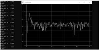
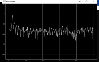
1 -The problem is as I run without changing any parameters the plot varry from picture 1 to picture 2,
picture 1
picture 2 .
2-My important problem is tha I put a device infront of sensor and when I use mmwastudio 3.0.14 For running Awr2243+DCA1000 with its defulat setting it is working properly and I can see amplitude and extract right data, but it is completely wrong with all the mmwave_dfp_02_02_03_01 examples .( I also used many config in mmwaveconfig.txt.)
So still I can not use mmwave_dfp_02_02_03_01 ,I also tested awr1243 settings with same problems.
in mmwave studio I set default parameters awr1243 and awr2243 StaticConfig-DataConfig-SensorConfig,
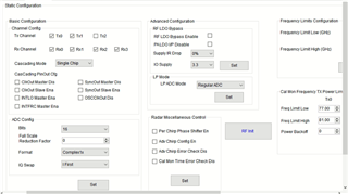
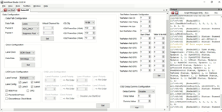
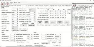
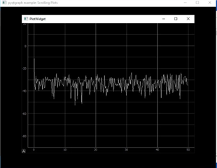
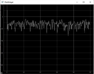
and also connect and trigger DCA1000.when I run my python The signal plot that is right is now this:
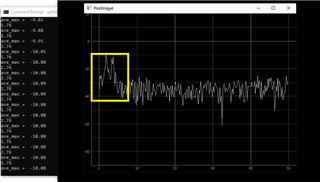
as you can see here are two amplitude that are not in DFP sample(parameters are as same s mmwave studio)
what is the problem???
could anyone help??
Thanks for your attentions.