This thread has been locked.

If you have a related question, please click the "Ask a related question" button in the top right corner. The newly created question will be automatically linked to this question.

AWR1843: Angle accuracy measurement report when 3 TXs are transmitting simultaneously at 0 degree phase beamforming.

Part Number: AWR1843

Hi TI,

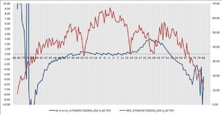
 Does TI have any measurement report for angle accuracy vs. angle on AWR1843BOOST such as "System Performance Measurement With the mmWave Sensor" Figure 6, especially when the 3 TX are beam formed to transmit at the same time with all the same 0 degree phase?

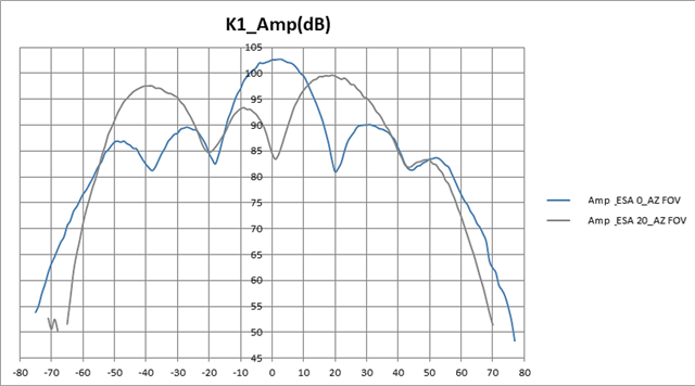
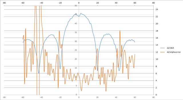
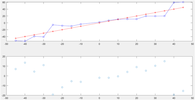
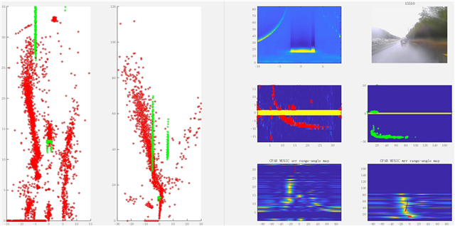
 We ask this because we find the angle accuracy becomes worse when we enable the 3 TX phase shifter to 0 degree at the same time, compared with the general MIMO without beamforming. What can be the root cause and how could we improve this?


  • Hi,

    Unfortunately we don't have such data.

    Have you performed the measurement when all 3TX are enabled but the phases shifters are not enabled?

    Thank you

    Cesar

  • Hi Cesar,

     We had the measurement as below pictures.

     In first picture, the blue color line was set at 3 TX simultaneously transmitting with all 0 degree. The grey color line is to shift the TX phase for +20 degree result. The y-axis is the SNR reading.

     The below 2nd picture shows with the angle accuracy (error) measurement in orange color line. The y-axis in right side is the degree of angle error. As you can see that the error can vary from 2 degree to 8 degree within +/- 20 FoV.


  • Hi,

    Please give me some time to check with extended team if there are any measurements available

    thank you

    Cesar

  • Hi,

    Actually I have some more question on your testing

    1)Did you perform these measurements by capturing raw data with DCA1000 board? Or did you use another method?

    2) When "The grey color line is to shift the TX phase for +20 degree result." what was the value programmed to the phase shifters

    3) In the 2nd Picture, what is the value programmed to phase shifters? Based on the blue line it seems that Tx Phase =0. Is this correct?

    Thank you

    cesar

  • Hi Cesar,

     Please see answers:

     1). Customer uses her own GUI to read back the SNR and angle data. The test is in chamber room with a 3cm size corner reflector set in boresight of AWR1843 device in 2.85m.

     2). The grey color line was just for testing to shift the angle by 20 degree modification from profileCfg. Please discard this first, since we didn't have its angle accuracy measurement. Because we found the angle error is larger when 3 TX are enabled together that we want to fix first.

     3). The three TX are enabled with 0 degree TxPhase as attached cfg file "R151-ESA_0 deg.cfg".

    R151-ESA_0 deg.cfg

  • Cesar, 

    May I know if you or extend team have any further information or report can share for our reference? 

    Meanwhile, may I know if the following attachment can be applied to solve the angle error as using 3TX simultaneously transmitting?

    spracv2.pdf

  • hi

    Have u tried this method? Do u have any result picture to show the calibration effect?

    I am also having this problem when I tried to test the AoA performance of AWR1843. Below is my test result using a corner reflector at an empty open field.

    Also, when I test a moving target which travelling a circle in front of our radar from right side to left side. It showed a discontinuous track as below. The left side picture full of red points was the object's track. It should be like a round circle, bu turn out to be a pattern like this. Some part of it, the track jumped from one angle straightly to another(like the right up part of this track). And the left part of this track the main lobe energy was totally leak to the side lobe which caused the second track route(which should not be exist).

    And, when I test the 'radar angle alignment 'using a road side guard rail, the result is showed below. I was trying to match the lidar point cloud and the radar point cloud when detect the road side guard rails. Like the picture shows below, the left side of it is also the guard rail points both from the radar(red points) and the lidar(green points).

    If the angle estimation performance was good, the red points(radar output) from both side of the road guard rail should at least be parallel. But the result showed a fairly big offset. The far left pic was from usrr mode, and the one next to it was from mrr. The result shows out that the offset was even larger at mrr mode.

    I am pretty sure this was caused by the angle estimation error now when I saw you guys' issue, So how can I fix this using some inherent method like radar calibration or some other method? 

  • Hi,

    Unfortunately I have not received feedback yet.

    I am checking again and will provide update in the next days.

    Here is the configuration I am checking with the systems team

    • angular error
    • all 3 TX enabled

    Thank you

    Cesar

  • Hi,

    I have discussed this issue with systems team.

    Could you please let us know if the board is configured to the third use case (highlighted)?

    Thank you

    Cesar

  • If the board is configured properly, than I think there is some uncorrected gain/phase mismatch between the Tx antennas which degrades the beamforming angle accuracy.

     Is it possible to perform following measurements:

    • Amplitude & phase of the received signal for a strong target at boresight with:
      • Tx 1 alone enabled
      • Tx2 alone enabled
      • Tx3 alone enabled
      • Tx1 & 2 enabled
      • Tx1 & 3 enabled
      • Tx2 & 3 enabled
      • Tx1, 2 & 3 enabled
  • Hi,

    Anybody have this test and upload data up to here?

    I am not very familiar with the development of this equipment.

    三个和尚没水喝吗?

    Besides, can anyone tell me how to make my reply as a independent one rather than placed below someone else's answer. Thanks.

  • Hi  Yanlong Yang,

     I will suggest you can create another new E2E question for your equipment setup question or the calibration difference. So it will not be mixed up here which is focusing on the angle accuracy under 3 TX transmitting simultaneously.

    Hi JY Su,

     Do you have comment on TI Cesar's question on your setting for the 1.0V mode? and would you be ok to provide the measurement data per Cesar's request?

  • Cesar,

    The board is configured to the third use case.

    I will perform following measurements this week. 

    • Amplitude & phase of the received signal for a strong target at boresight with:
      • Tx 1 alone enabled
      • Tx2 alone enabled
      • Tx3 alone enabled
      • Tx1 & 2 enabled
      • Tx1 & 3 enabled
      • Tx2 & 3 enabled
      • Tx1, 2 & 3 enabled

    By the way, we also need you to show us the beamforming result by your platform to clarify the performance about this function as using at MRR application

    JY

  • Hi Jesse Wang,

    I believe I am facing the same problem with you guys. I am feeling satisfied when I saw your replies this week cause no body answered Cesar last week.

    Hope you would have good result this week , I am keen to see some conclusion now.

    Best regards

  • Thank you

    Will you be collecting raw data?

    The MRR demo does not perform calibration, so this could be the issue that is seen with the demo

    thank you

    Cesar

  • Hi

    I have done the experiment under a 5GHZ chamber like below with a single corner reflector in front of our radar equipment 5 meters away. The freq band does not match well but the chamber still provide a clean environment.

    The data can be analysised by the code  under:

    C:\ti\mmwave_studio_02_01_01_00\mmWaveStudio\MatlabExamples\singlechip_raw_data_reader_example.

    The data has two format, one is '.bin', one is '.json'. The 'bin' files are the data and the 'json' files are the parameters. What you should do is:

    0. the files are like below:

    'tx0' means using 0 tx and 4 rx

    'tx01' means using 01 yx and 4 rx

    1. put the 'bin' files into 'C:\ti\mmwave_studio_02_01_01_00\mmWaveStudio\PostProc\'

    2. put the 'json' files into 'C:\ti\mmwave_studio_02_01_01_00\mmWaveStudio\JSONSampleFiles\18xx\'

    3. open matlab and direct to 'C:\ti\mmwave_studio_02_01_01_00\mmWaveStudio\MatlabExamples\singlechip_raw_data_reader_example\'. You will see three files: 1.'rawDataReader.m', 2.'verify_data.m', 3.'readme.txt'.

    4. use this command to call the data read function:

    rawDataReader('C:\ti\mmwave_studio_02_01_01_00\mmWaveStudio\JSONSampleFiles\18xx\tx0.setup.json', 'C:\ti\mmwave_studio_02_01_01_00\mmWaveStudio\PostProc\tx0.bin', 'tx0.mat', 1);

    and the results are like:

    then u can compute the phase or anything you like.

    singleTXlikeTestData.rar

  • Thank you

    We will review the data

    Cesar

  • Hi,

    any update?

  • Hi,

    Sorry for the delayed reply. 

    I suspect some capture issue in the setup. The time domain data is expected to be a sine wave. Instead, we see mostly zeros in time domain with some random glitches. Range profile (Frequency domain) should show a strong peak due to the corner reflector. However, we see mostly noise. 

    Can you please cross check the data capture to see if something is wrong?

    Thanks,

    Shankar

  • OK,

    some error may occur in it

    I will update this data tomorrow

  • sorry,

    I didn't do the test last week as I got really busy the last days, but anyone else has the test or analysis?

    thanks

  • Cesar,

    Recently, we verify the same case as using 6843. The degree of angle error is as the following 

    This result show the case of 6843 will not vary so much vs. 1843. 

    % Maximum Range:23.2m,               Range Resolution:20cm,        Maximum Velocity:135km/h,           
    % Velocity Resolution:1.065km/h,     Sweep Bandwidth:909.1MHz,     202.9 KHz/meter,   
    sensorStop
    flushCfg
    dfeDataOutputMode 1
    channelCfg 15 7 0
    adcCfg 2 1
    adcbufCfg -1 0 1 1 1
    lowPower 0 0
    profileCfg 0 61.5 3 4.4 29.89 0 0 30.42 -1 128 5300 0 2 30
    chirpCfg 0 1 0 0 0 0 0 7
    frameCfg 0 1 128 0 50 1 0
    guiMonitor -1 1 1 1 0 0 1
    cfarCfg -1 0 2 16 5 4 0 12 1
    cfarCfg -1 1 2 16 2 4 1 12 1
    multiObjBeamForming -1 0 0.1
    calibDcRangeSig -1 0 -1 1 256
    clutterRemoval -1 1
    compRangeBiasAndRxChanPhase 0.0 1 0 1 0 1 0 1 0 1 0 1 0 1 0 1 0 1 0 1 0 1 0 1 0
    measureRangeBiasAndRxChanPhase 0 1.5 0.2
    aoaFovCfg -1 -90 90 -90 90
    cfarFovCfg -1 0 0.4 23
    cfarFovCfg -1 1 -37.5 37.5
    extendedMaxVelocity -1 0
    CQRxSatMonitor 0 3 11 121 0
    CQSigImgMonitor 0 127 8
    analogMonitor 0 0
    lvdsStreamCfg -1 0 0 0
    bpmCfg -1 0 0 0
    calibData 0 0 0
    sensorStart
    

    May I know the possible reason why? 

    JY

  • Hi,

    Did you use the 6843ISK board for testing?

    It is difficult to say why the performance is different. The 6843ISK and 1843BOOST antennae should have similar designs

    thank you

    Cesar

  • Sir,

    This 6843 case is also based on our design. Our 1843&6843 design case is based on almost the same PCB layout which are only different at antenna (77G vs. 60G) & RFIC(1843 vs. 6843) chipset. FYI.

    JY