This thread has been locked.

If you have a related question, please click the "Ask a related question" button in the top right corner. The newly created question will be automatically linked to this question.

DCA1000EVM: Followup to Data Read with Zeros Question

Part Number: DCA1000EVM

Hello,

I was wondering if there was ever any progress on my question that I asked 5 months ago and is now locked. There was never a reply after getting the someone will reply soon message. The tool said to click this button to add to the thread but there is nothing from the previous thread in this post so if I need to copy and paste that information again please let me know.

Regards,

Ted

  • Hi,

    I think this is the thread you have in mind.

    We apologize for dropping this thread.

    We will review it and get back to you this week.

    thank you

    Cesar

    https://e2e.ti.com/support/sensors-group/sensors/f/sensors-forum/1009962/dca1000evm-raw-data-output-curiosity

  • Cesar,

    Yeah that is the one. No worries on the delay my attention got diverted during that time so it all worked out in the end.

    I would like to update that I did get a newer version of mmWave Studio, updated all of the drivers, and noticed the same error occurring. In the TI GUI the data displays as it should and looks good. But when I go to read it in MATLAB those zeros are still present. I started to wonder if maybe the data type that I should be reading in changed? The old code example in the "Mmwave Radar Device ADC Raw Data Capture" document reads data as 'int16'. With the new version of mmWave Studio a new bit of code was provided titled "rawDataReader.m" and buried down in it the line that reads the values is 'uint16=>single'. Using this data type also has the same zeros as my previous post.

    I don't want to use the rawDataReader code as it has over 1300 lines of code and at this stage all I want is to open the binary file and have it match the data format as listed in the "Mmwave Radar Device ADC Raw Data Capture" document.

    Regards,

    Ted

  • Hello Ted, 

    Extremely sorry for the delay due to holidays. 

    Now I 'm just trying to understand the differences between your two experiments. At first, you got a file size of  4096 KB and then you got 8192 KB. Are you completely sure you did not change anything? This can include any software platform such as a version of mmWave studio, DCA1000 firmware, radar configuration or anything....

    Did you change the number of samples? Mostly we see the data is zero filled when a few frames are missing.

    It is possible if your data rate requirements are higher that the bandwidth supported. There is a zero fill utility, that will fill in dropped frames with zeros if that happens. 

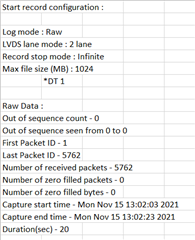
    Information about dropped frames is also provided in the mmWave Studio log. It is something of this sort : 

    ar1.PacketReorderZeroFill("C:\\ti\\mmwave_studio_02_01_01_00\\mmWaveStudio\\PostProc\\adc_data_Raw_0.bin", "C:\\ti\\mmwave_studio_01_00_01_00\\mmWaveStudio\\PostProc\\adc_data.bin", "C:\\ti\\mmwave_studio_01_00_01_00\\mmWaveStudio\\PostProc\\pktlogfile.txt")
    [14:19:06] [RadarAPI]: Packet Reorder Utility process completed!
    [14:19:11] Reordering required : NO
    [14:19:11] Packet loss : NO
    [14:19:11] Number of packets received : 10803
    [14:19:11] Number of zero filled packets : 0 

    Regards,

    Ishita

  • Ishita,

    Recently I had my laptop refreshed and had to download all of the software and drivers again so my original post comparing the two files is no longer something I can do. That being said using the most recent version of mmWave Studio with the original setting files still produces the same issue as before. The TI GUI post processing feature processes the data just fine and shows heat maps that make sense when considering the ranges I place targets at and there is data for all 32 frames. But when I look at the .bin file those zeros are still there. According to the data structure that I referenced in my original post it makes no sense to have a 0 as every other number. That is not the way the LVDS lane organizes the data, and if I were dropping frames would there not be a block of 0's since the frames are concatenated one after the other in the data structure? Nothing is interleaved so for something being dropped to produce a zero every other number makes no sense to me. Also I checked my log file it is says there was no reordering done, which according to the new mmWave Studio documentation is automatically run when you click post processing.

    The fact that the TI GUI still processes the data leads me to believe all of my data is present but something changed with the file format that I am not aware of and am trying to figure out. I am reading them in as int16 values which I found in a snip of code a DCA1000 document. In the newer version of mmWave Studio a code titled "rawDataReader.m" was provided that is much more complicated than the original code snip and in that file the data is read in like this

    I have tried this and nearly every other format in the books and nothing I have tried will eliminate those zeros from the file. And like I originally stated simply pulling them out of the data made my heat maps no longer match the heat maps produced my the TI GUI. My original code followed the file structure description from the DCA1000 reference material and worked perfectly with the older version of mmWave Studio.

    I know that is a lot of words but I want to try to pain the clearest picture of what I have tried so we can find a solution to this odd issue. I would not put is past that something changed I am not aware of and I am doing something dumb when loading in the data. Hope this helps some.

    Regards,

    Ted


  • Hello Ted, 

    Yes, this looks a little strange. Let me consult on this issue internally and get back to you in a day or two. 

    Regards,

    Ishita

  • Thanks for looking into it. This is very strange. I attached the .bin file as a .txt since I can't load in a .bin file. Change the extension back to .bin and it should work on your end. If you want it sent directly send me an email address and I can send it to you. Also attached is the log file.

    adc_data.txt


    15-Nov-2021 12:36:53: IsFPGA:,0,0,
    15-Nov-2021 12:36:53: C:\ti\mmwave_studio_02_01_01_00\mmWaveStudio\RunTime,0,
    15-Nov-2021 12:36:56: API:select_capture_device,DCA1000,0,
    15-Nov-2021 12:37:20: API:select_chip_version,AR1642,0,
    15-Nov-2021 12:37:38: API:select_chip_version,AR1642,0,
    15-Nov-2021 12:37:54: API:select_chip_version,AR1642,0,
    15-Nov-2021 12:38:03: API:ChannelConfig,2,1,0,
    15-Nov-2021 12:38:03: API:AdcOutConfig,2,1,0,
    15-Nov-2021 12:38:03: API:DataFmtConfig,1,2,1,0,1,0,
    15-Nov-2021 12:38:12: API:DataPathConfig,1,1,0,2,0,
    15-Nov-2021 12:38:13: API:LvdsClkConfig,1,1,0,
    15-Nov-2021 12:38:13: TSW1400 Sampling rate : 600000000 7500000,0,
    15-Nov-2021 12:38:13: API:SetHsiClock,9,0,
    15-Nov-2021 12:38:15: API:LaneConfig,1,0,
    15-Nov-2021 12:38:15: API:LvdsLaneConfig,0,1,0,
    15-Nov-2021 12:38:30: API:ProfileConfig,0,1467074277,300,186,4800,0,0,259,0,256,6000,0,0,30,0,
    15-Nov-2021 12:39:08: API:ChirpConfig,0,0,0,0,0,0,0,2,0,
    15-Nov-2021 12:39:20: API:select_capture_device,DCA1000,0,
    15-Nov-2021 12:39:29: API:EnableTestSource,0,1,0,
    15-Nov-2021 12:39:29: API:FrameConfig,0,0,32,128,120000000,0,512,0,
    15-Nov-2021 12:39:29: API:AdvancedFrameConfig,1,0,0,0,1,128,120000000,0,1,1,120000000,0,0,0,0,0,0,0,0,0,0,0,0,0,0,0,0,0,0,0,0,0,0,0,0,0,0,0,32,0,0,0,0,0,0,0,0,0,0,0,0,0,0,0,0,
    15-Nov-2021 12:40:12: API:SensorStart,0,
    15-Nov-2021 12:46:45: API:update_num_adc_files_and_frames,1,32,1,0,
    15-Nov-2021 12:48:22: API:SensorStart,0,
    15-Nov-2021 12:48:49: API:update_num_adc_files_and_frames,1,32,1,0,
    15-Nov-2021 12:50:55: API:SensorStart,0,
    

    Regards,

    Ted

  • Thanks for the information Ted. 

    Having the ADC bin file will definitely help.

    Regards,

    Ishita

  • Ishita,

    Any update on the ADC file?

    Regards,

    Ted

  • Hello Ted, 

    What is the mmWave Device you're using here?

    From your configuration, I can see you're only using one LVDS lane to send out the raw ADC data, whereas the DCA1000 has two channels. The channel that isn’t connected has all the zeros. So this is not an error, it's just the data based on your lane configuration. You can ignore all the zeros while processing. 

    Hope that makes sense. 

    Regards,

    Ishita