This thread has been locked.

If you have a related question, please click the "Ask a related question" button in the top right corner. The newly created question will be automatically linked to this question.

MMWAVEICBOOST: How to configure UART ports?

Part Number: MMWAVEICBOOST
Other Parts Discussed in Thread: MMWAVEPOEEVM,

Hello everybody,

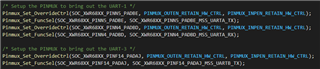
I want to use MMWAVEPOEEVM. For that, I want to read data from the UART of MMWAVEICBOOST to send via POE.

How the UART of the booster is configured to send data to the PC without POE?

Thanks in advance.

Thanks and regards,

Aleena N A

  • Hello,

    The MMWAVEICBOOST has a XDS110 micro USB connector. This connector holds two UART channels. One for configuration + confirmation, and another for output processed data. These there UART lines are routed through the 60-pin connector to the radar EVM. So if you want to get the UART signals routed to the 40 pin connectors that would connect to the MMWAVEPOEEVM module then you would need to change the 12 mux switches on the MMWAVEICBOOST to make that happen.

    Best regards,

    Connor Desmond

  • Hello Connor,

    Okay. There are UART_0 and UART_1. Which are the pins in MMWAVEICBOOST corresponding to this UART's?

    Thanks and regards,

    Aleena N A

  • Hello,

    I would suggest looking at the schematic for your radar EVM as well as the MMWAVEICBOOST. These schematics will provide the information of how the signals are routed depending on the state of the 12 mux switches on the MMWAVEICBOOST. Here  is a link to the page which has the schematic in zip file to download:

    https://www.ti.com/lit/zip/swrr164

    If you want to know what the PIN mux for the UART is I would suggest looking at something similar to the image below and align that information with the datasheet to understand physically what pin (ball in this case) is associated with the software instances of the UART peripheral.

    main.c/mss_main.c

    Best regards,

    Connor Desmond