This thread has been locked.

If you have a related question, please click the "Ask a related question" button in the top right corner. The newly created question will be automatically linked to this question.

AWR1843AOPEVM: ROS driver: Coordinate frames 1843AOP 6843AOP

Part Number: AWR1843AOPEVM

Hi

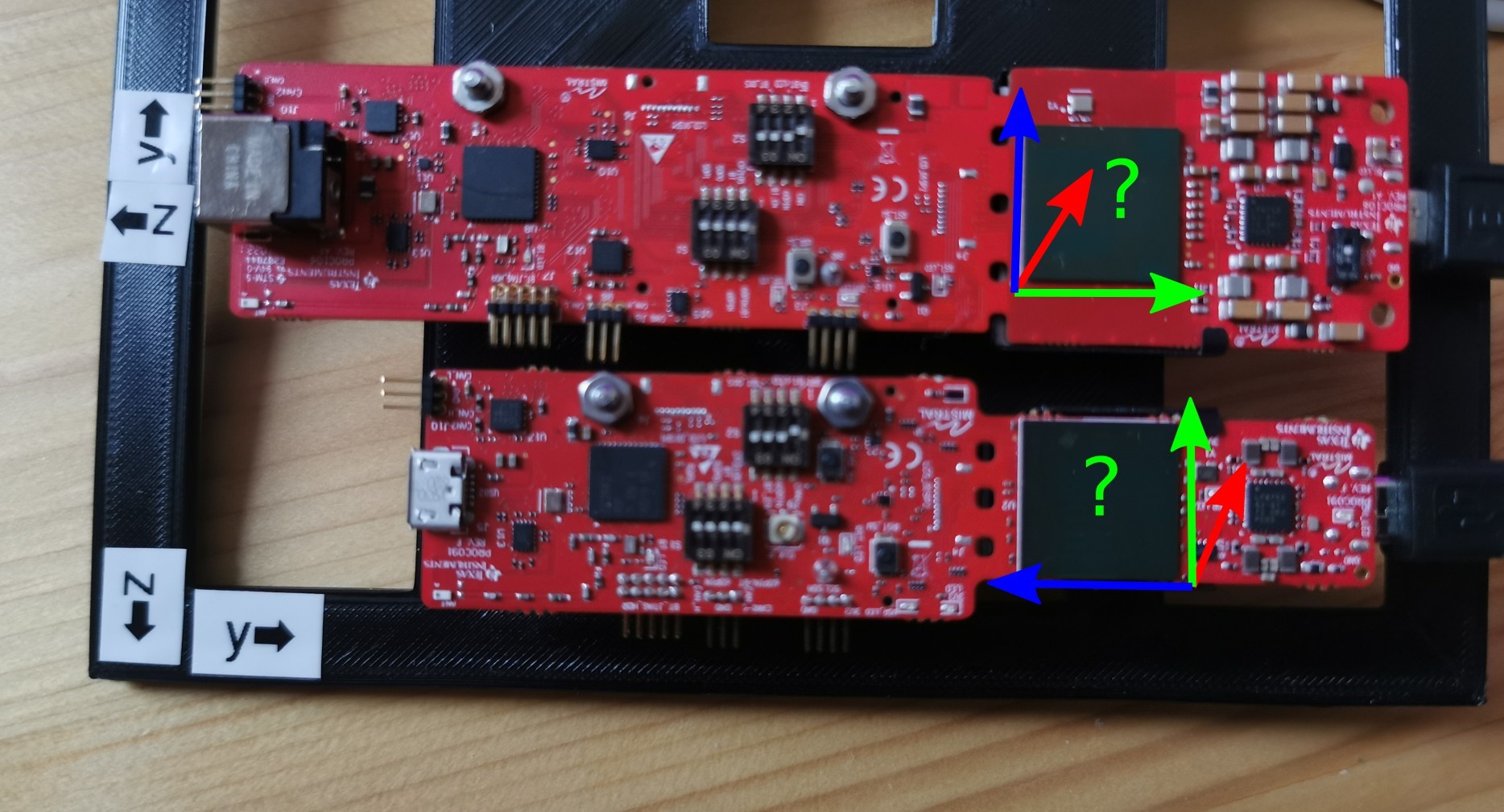
I have an 1843AOPEVM and and 6843AOPEVM and am using the ros driver. To me, it seems like the two devices have their coordinate system placed differently. Can anyone from engineering confirm this?

Here is a sketch of the setup with the axes labelled (which are probably wrong).

Thx for your insights

radar frames

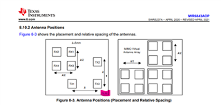
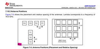
edit: I found these images on the user guides:

Where are the axes labelled for the 1843AOP?

Also, where is the y-axis for the 6843AOP? Left or right-handed frame?

  • Hello Tim,

        Yes, Antenna configuration and placements are different between two designs.

    Please refer to the Data sheets for the Antenna placement with respect to A1 ball position. 

    Below is the configuration of the Antenna w.r.t to A1 ball for the 6843AOP designs. 

    Below is the configuration of the Antenna w.r.t to A1 ball for the 1843AOP designs. 


    Please note there is change in the virtual antenna configuration as well. 

    Thanks and regards,

    CHETHAN KUMAR Y.B.

  • Great! thanks for the quick reply...makes sense to me. Based on the screenshots you shared, is there a way to tell the axes based on the antenna config? i.e. where are the x-, y- and z-axis? I will mark the answer as solved, if you have an answer to that, thx! Also: Are you using right- or left-handed coordinate frames?

  • Hello Tim,

         Coordinate system depends application system. 

    You could refer to below tuning guide which provides coordinate system used in our demos for ISK, ODS and AOP devices. 1843AOP  would be rotated by 90 Deg counter clock wise w.r.t 6843aop. 

    Tuning Guide - Detection Layer

    Also you could refer ROS demos from the below TI resource explore

    Robotics

    Thanks and regards,

    CHETHAN KUMAR Y.B.

  • Thx for the reply! I have just gone through the tuning guide and only found information about the 6843AOP (and the variants ISK & ODS), but nothing about the 1843AOP e.g. in Figure10. Where do you infer the 90° CCW rotation? Is there an image of the virtual antennas for 1843AOP and 6843AOP?

    Also, the ROS documentation does not have any info about the frames...only in the driver code, but that gives me differents frames for the 1843AOP vs 6843AOP. Thx!

  • Hello Tim,

        You are right in the turning guide only 6843AOP is provided. 1843AOP is targeted for different applications specifically for Automotive and Robotics. Link is provided for the reference of coordinate system for 6843AOP.

    Above diagram has the virtual antenna array,  Pin Marking A1 highlighted in the images shows the position of Antennas w.r.t to A1 marking on the chip. 

    Physically on the device you would find white dot and that would be corner for the A1 ball location. Once you have identified the A1 corner, Antenna locations are fixed w.r.t to that as shown in the above diagram. 

    If you take 6843AOP antenna as reference w.r.t to A1 ball location, 1843AOP antennas are rotated by 90 CCW. 

    Virtual antenna also shown in the above diagram, For each of the Tx corresponding Rx virtual antenna represented by square/rectangular box and square box inside.  

    Thanks and regards,

    CHETHAN KUMAR Y.B.

  • Turned out that the frames are not only rotated, but the 1843 is using a LH frame, whereas the 6843 uses a RH frame Slight smile

    Thx for your assistance and support!