This thread has been locked.

If you have a related question, please click the "Ask a related question" button in the top right corner. The newly created question will be automatically linked to this question.

IWR1843BOOST: Range and phase calibration vs. temperature

Part Number: IWR1843BOOST

Hi,

I am using the demo from sdk_03_05_00_04 to generate the calibration coefficients with the following CLI command :

measureRangeBiasAndRxChanPhase

I also use the special profile_calibration.cfg file for that.

I am using a small corner reflector as a target at ~2m.

When I plot the evolution of the coefficients phase at room temperature (~10°C) during ~12 hours, I obtain a slow drift of absolute phases :

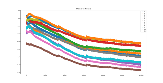
The relative phases are relatively constant.

When I do the same with a 60°->20°C temperature sweep (nonlinear sweep : only passive cooling), there are transitions where the relative phases change a lot (let's say the brown curve is ahead of the blue one and after the transition it is the opposite) :

I understand the radar performs continuously self-calibration as described in SPRACF4B, which would explain the transitions.

You can see that the phase correction coefficients will depend a lot on the temperature selected.

Are the coefficients valid only for the same temperature with the following CLI command compRangeBiasAndRxChanPhase ?

Or do we need to perform this operation only at room temperature, and the chip will compensate at different temperatures ?

Best regards,

Massimo


  • Hi Massimo, 

    You only need to perform this operation once. Just to give a brief background on this, the Rx gain or TX power (or any other RF/Analog aspect) may vary from device to device due to manufacturing process variations and also across temperature. Hence, the purpose of calibration is to ensure the RX gain and output power are maintained as configured by the user despite variations in process and temperature.

    To achieve this, the internal processor adjusts the mmWave circuit configurations at initialization (to mitigate effects of process variation) and periodically at runtime (to mitigate effects of temperature drifts).

    Regards,

    Brennan

  • Hi Brennan,

    Thank you for your answer.

    I understand the goals of the calibration you detailed.

    There is still one thing I do not understand:

    - The calibration coefficients are measured once. They compensate for the variability of the manufacturing process of the chip and PCB traces.

    - These coefficients seem to be heavily dependent on the temperature at which the calibration is performed.

    - These coefficients are sent to the radar at every startup through CLI. If the radar starts at a temperature different from the one the calibration was made, I do not understand how this could compensate properly as these coefficients are sent without any information about the temperature at which they have been measured.

    Best regards,

    Massimo

  • Massimo, 

    The CLI command compRangeBiasAndRxChanPhase takes into account the temperature at the time of calibration, and sets the baseline for future measurements.  The automatic RF calibration procedure will adjust for temperature changes in future measurements.

    Regards,

    Brennan

  • Hi Brennan,

    As the calibration coefficients measurement is only implemented in the 'out of box demo' and not in the traffic monitoring lab, we first flash the demo firmware and measure the coefficients. After that, we flash the traffic monitoring lab and send the coefficients through CLI.

    I don't understand how the temperature information about the coefficients is stored in this process.

    Best regards,

    Massimo

  • Massimo, 

    The Traffic Monitoring lab is essentially the Out of Box Demo with tracking on top of it.  If you send the CLI command compRangeBiasAndRxChanPhase, the coefficients will be stored in the same way.  The measurement command is only supported in the base Out of Box Demo, but the other demos (such as Traffic Monitoring) will all accept the coefficients as inputs.

    This shows the cfg parameter function for this in the Traffic Monitoring demo CLI file (C:\ti\mmwave_industrial_toolbox_4_9_0\labs\traffic_monitoring\18xx_68xx_traffic_monitoring\src\mss\mmw_cli.c).  The function on the third line of this screenshot stores the calibration data.  You can trace the data from there.

    Regards,

    Brennan

  • I will look into it, thank you.

    Best regards,

    Massimo