This thread has been locked.

If you have a related question, please click the "Ask a related question" button in the top right corner. The newly created question will be automatically linked to this question.

AWR1843BOOST: Received signal separation on BPM MIMO

Part Number: AWR1843BOOST

Hello,

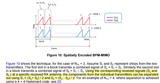
I see the MIMO document introduces that BPM can set the phase.

I notice that this separation method .

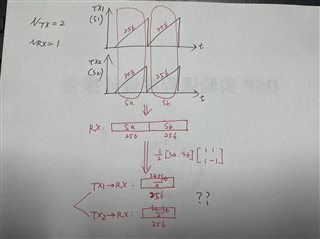
what I understand this case:  Assuming that each chirp has 256 sampling points, two antennas transmit two chirps, and one receiving antenna receives 256*2 data, I need to separate TX1-Rx and TX2-Rx, and there should be two groups of 256*2 data, so how should I get it? 

According to the method in the document, I only got a column of 2*256 data. Am I making a mistake? 

Is there any problem with my understanding according to the following graph? 

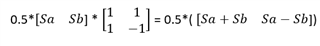
In the graph, I multiply the received data by a 2*2 Hadamard matrix to get 2*512 data. Is that a problem?  If, according to my understanding, bothTX1-RX parts are equal to 0.5* (Sa+Sb), how can I solve this problem? 

Thank you  

  • Supplement: Will the two pulses become only one pulse after decoding when separated? Will the data be compressed?  

  • Hi Pengyang,

                        If I understand your setup correctly, you are trying out BPM MIMO on AWR1843BOOST with NTx=2 and NRx=1 right? 

                        So the column of 2 x 256 data which you get must be right only, as in BPM MIMO both Tx are transferring data at the same time, so as mentioned in the document both the chirps of Tx gets added up and you have only one receive antenna, therefore you get only one signal for first chirp. Similarly when the chirp is transmitted by both Tx's (now its subtracted due to BPM), you get only one signal at Rx.

                         Therefore, for 2-chirps of 256 ADC samples, you get a 2 x 256 data (not sure if the data can also be 256 x 2 but it depends on your parameters I guess). Then to separate the data of transmitters, I think you can do something as mentioned in the document wherein for Tx1 data you could use S1 = 0.5*(Sa+Sb) and for Tx2 data you could get by S2 = 0.5*(Sa-Sb).

                         I think if you consider that signals combine at Tx and at Rx we get 2 x 256 matrix of data (or 256 x 2 based on setup) corresponding to 2-chirps, the equations in the graph would change to:


                       So this lets us obtain the equations in the document.

                       Data won't be in compressed state and all. And as mentioned in the document, this decoding steps must be done after Doppler FFT and prior to angle FFT.


                       Let me know if this solves your queries.

    Thanks and Regards,

    Akshay.

  • Hello, thank you for your reply. I understand what you said, but I have a few questions:
    please look at the following diagram.


    1.Are the two 256 datas in the end of the graph decoded at last?  Is 2*512 decoded to get 2*256 data?

    TX1 emits two pulses (512 samples), but does TX1->RX actually separate only one pulse of data (256 samples)?  I don't really understand can you elaborate on that? 

    2. If according to this, if the 4 antennas uses 4*4Hadamard matrix encoding to transmit orthogonal signals, does every four pulses decode only one pulse data?

    3.If only one antenna emits two pulses, 512 samples should be received.  If 2 antennas emits two pulses at the same time, after decoding,will the amount of data received from each antenna  reduce by half?

    Thanks and Regards,

    pengyang

  • Hi Pengyang,

                       For question1: If two Tx transmit 256 ADC samples at the same time, they get added added up and at the receive antenna receive as a single signal right? So that is the case here. So as you transmit two chirps, you get 2 x 256 Rx data at receiver.

                      For questions 2 and 3, I think you would need to give me sometime to think and get back maybe by Tuesday.

                      Also, can you please mention the reason why you are trying this experiment with 1-Rx, MIMO must have multiple Rx's right? Maybe are you just trying to get the understanding of MIMO by using bare minimum number of chirps, 2-Tx and 1-Rx etc.? Please let me know if you require more support regarding understanding of BPM MIMO theoretically or device implementation or both.

                    Please feel free to ask more questions if you have anymore

    Thanks and Regards,

    Akshay.  

  • Hello, thank you for your reply.

    1.In fact, my essential question is question 3: Why does each antenna send two pulses(total of 512 ADC samples), for example for TX1 to RX, the data obtained by the receiving antenna should be half (half of 512 ADC samples)?  I don't understand which time point of the 256 samples corresponds to which chirp is emitted? 

       My goal is to understand MIMO, but I don't yet understand the data format that 2TX-1RX gets. 

    2.Supplement: You said that this step should be decoded after Doppler FFT. I remember that 1TX-1Rx can use range-FFT and Doppler FFT directly for distance and velocity.  But 2TX-1RX has no decoding before, the received data is multiple transmitting antenna data mixed in a row, can it directly use range-FFT and Doppler FFT to solve the distance and speed?  Why not decode first and then use range-FFT and Doppler FFT?  

    Thanks and Regards,

    pengyang

  • Hi Pengyang,

                        Thanks for your patience.

                         Let me explain to you from the beginning to give you answer for question3. So in your BPM MIMO setup there are 2-Tx, 1-Rx, transmitting two-chirps in total Sa and Sb with ADC samples of 256. 

                         According to the TI document on MIMO, fig.10 depicts two Tx transferring Sa and Sb, where Sa=S1+S2 and Sb = S1-S2. So at the instant Sa is transmitted, S1 data of 256 samples from Tx1 and S2 data of Tx samples get added to become a single signal and is received at Rx as 1x256 for Sa alone. Similarly the same happens for Sb also, and we get 1 x 256 samples. So the net signal received at Rx after Sa and Sb transmission is 2 x 256 (the columns of data that you had received initially) corresponding to 2-chirps (one for Sa and other for Sb) of data and 256 ADC samples.

                       I think you maybe getting confused because the data size is very less. Now say for instance, there are:

    • 2-Tx, 2-Rx and we transmit total 128 (64 Sa and 64 Sb) chirps of data with 256 ADC samples. We will be receiving at Rx1, 128 x 256 data and at Rx2, 128 x 256 data corresponding to 128 chirps and 256 samples.
    • So we have 2 x 128 x 256 data at the two Rx's combined. Now we apply Range FFT and Doppler FFT after which we get 128 range bins and 256 Doppler bins at two Rx's.
    • Then in one of the Rx, the odd chirps of data 1,3,5...127 of 64 Doppler bins will be taken together to form 64 x 256 and similarly 64 even chirps will be taken together and we get 64 x 256 data. Then we demodulate to get Tx1-Rx1 data and Tx2-Rx1 data.
    • So we get 2 x 64 x 256 data at Rx1 corresponding to two Tx's. The same thing happens for the next Rx2 also, therefore we get 4 x 64 x 256 data finally at 2-Rx corresponding to 2-Tx. 

                So even if 4-antennas transmit 4-chirps of data, there would be Sa, Sb, Sc and Sd and it would finally get decoded to only one chirp from each Tx.

                So the data format in BPM MIMO is (number of virtual antennas x number of Sa/Sb/Sc/Sd x ADC samples). Number of virtual antennas = Num Tx * Num Rx. number of Sa/Sb/Sc/Sd can also be considered as number of blocks as the BPM MIMO document portrays. Where in for 2-Tx, a block has Sa and Sb.

                This decoding has to be done before Doppler FFT as there will be a phase induced velocity change if the objects in the scene are in motion. So there needs to be Doppler correction that needs to be done before decoding this. And for this decoding we would need the velocity of the object which can be only obtained after Doppler FFT.

              Let me know if you have any further questions.

    Thanks and Regards,

    Akshay.  

  • HI,

    Thank you very much.I think I get it.

    By the way,how can I use matlab to rebuild Range-Azimuth Heat map like GUI ?

    do you have some detail steps?

    Thanks and Regards,

    pengyang

  • Hi Pengyang,

                        Which GUI are you referring here? Is it the one in mmWave studio or something else?

    Thanks and Regards,

    Akshay.

  • HI,

    I use matlab to rebuild Range-Azimuth Heat map like mmWave studio .Like this:

    do you have some detail steps?

    Thanks and Regards,

    pengyang

  • Hi Pengyang,

                         Yes so from the data that you have collected you would need to apply 2D-FFT along the ADC samples and the number of chirps to get range-doppler heatmap. Here are the steps for getting to range-azimuth heatmap:

    1. Apply range-FFT along the number of ADC samples.

    2. Then Doppler FFT along the the chirps. Thus with this 2D-FFT is done.

    3. The you would need to apply 2D-FFT across all the virtual antennas.

    4. Then take the zero Doppler values of all the range bins to obtain the range-azimuth heatmap.

                         Let me know if you have any questions on this

    Thanks and Regards,

    Akshay.

  • HI,

    Thank you for your patience and help.I think I get it.

    But I find new questions about "near-field & far-field":

    1.If my goal is to do a range-Azimuth heat map of a moving car, 8 or 9 meters away from the radar, do I have to consider the question of near field or far field?

    2.I found a section of matlab code in one of the forums . I didn't quite understand what he was trying to do in his code, and what was his NearEndCorr? 

    Can you help me if you understand?  

    AWR1642BOOST: How to calculate azimuth heat map - Sensors forum - Sensors - TI E2E support forums

    3.Can you give me some tips on how to do near field or far field correction  

    Thanks and Regards,

    pengyang

  • Hi Pengyang,

                       Thanks for your questions. But on these topics, I would request you to start a new thread for tracking questions from our end. So I am closing this thread now. Request you to please start a new thread on the questions you have asked last.

    Thanks and Regards,

    Akshay. 

  • HI,

    Thank you.I have started a new thread.Can you give me the answer?

    Thanks and Regards,

    pengyang

    (1) AWR1843: "near-field & far-field" of Range-Azimuth Heat map - Sensors forum - Sensors - TI E2E support forums

  • Hi,

         Thank you. I will look into it.

    Thanks and Regards,

    Akshay.