This thread has been locked.

If you have a related question, please click the "Ask a related question" button in the top right corner. The newly created question will be automatically linked to this question.

LDC2114EVM: out0 lights just connecting to USB port

Part Number: LDC2114EVM
Other Parts Discussed in Thread: LDC2114,

Hello,

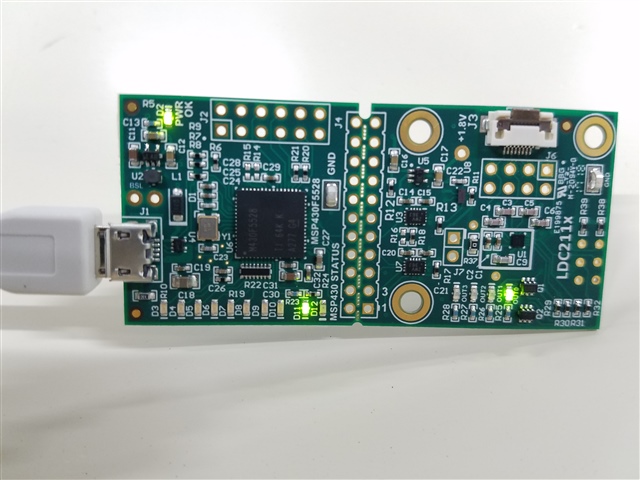
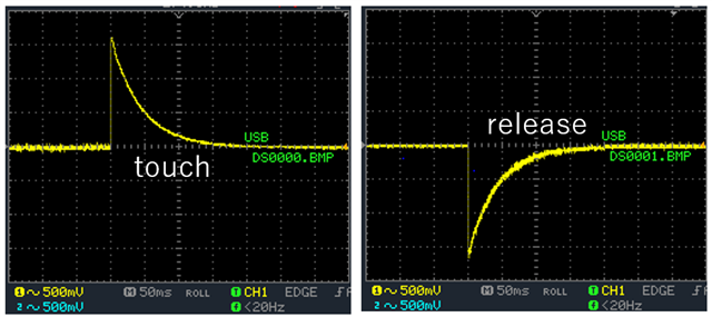
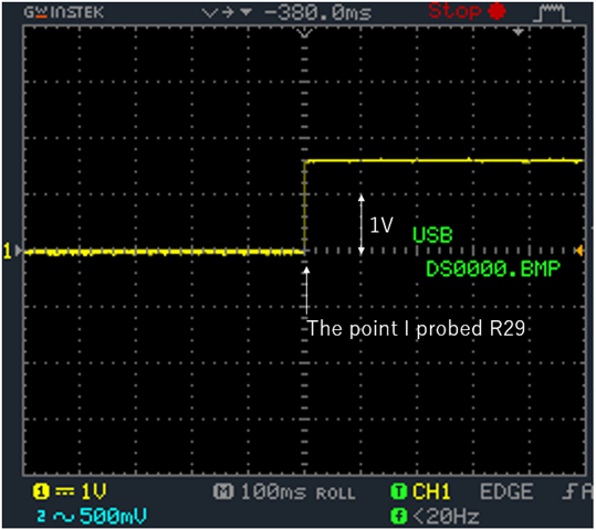
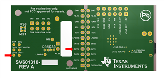
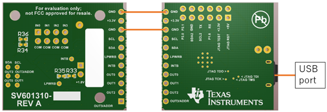
A problem happened when I used LDC2114EVM. I would like you to give me some advice. I was using LDC2114EVM making trackpad demo. First, LDC2114 worked properly. But not long after that, out0 lighted just when it was connected to USB port. I think out0 should light only while a corresponding sensor is acting. Is this broken? Can you fix it? 

Best Regards,

  • Hello, 

    What is the value of the OPOL_DPOL register? This controls the polarity of the OUTx pins and determines whether the LED will be on normally or during a press event. If changing that register does not solve the issue, can you try performing a software update to the EVM through the GUI? 

    Best Regards, 

    Justin Beigel

  • Hello,

    Thank you for your reply. How can I chack the value of the OPOL_DPOL register? Do I have to install Sensing Solutions EVM GUI to see it?

    Best Regards, 

  • Hello, 

    You will either need to install the GUI or communicate to the device over I2C using an external controller. 

    Best Regards, 

    Justin Beigel

  • Hello,

    I installed the GUI and tried to check the value of the OPOL_DPOL register. But I could find only the value of OPOL. Is this the value I should check? If that is the case, what value should I write to turn off out0 LED?

    Best Regards, 

  • Hello,

    The Engineer specializing in supporting LDC devices is currently on vacation, please expect a response after the holidays.

    You are correct, the value of OPOL is where you should check. 

    Here is the register contents for the OPOL_DPOL register. 

    Thank you,

    Jacob

  • Hello,

    Thank you for your reply. I understand your situation. I tried both changing the OPOL to 0xf0 and installing the firmware "EVM_LDC2114_(D3_D10_prox)".  However, out0 kept lighting. What should I do next?

    Best Regards, 

  • Hello,

    Thank you for the additional information. 

    The Engineer supporting this device will continue the debugging efforts upon return from vacation.

    I appreciate your patience.

    Thank you,

    Jacob

  • Hello,

    Has the engineer supporting this device returned from vacation yet?

    Best Regards,

  • Hello, 

    Does the out0 diode stay lit during normal operation of your demo as well? If you probe at R29, what voltage do you get? 

    Thank you, 

    Justin Beigel

  • Hello,

    I do not know if it stays lit during normal operation of demo because I have not finished making demo. This is the voltage when I touched R29 and released respectively.

    Best Regards,

  • Hello, 

    R29 is tied to the output of the IC and should be at a steady voltage around 1.8V or at 0V depending on the state of the button press. Since yours seems to decay to 0 and goes negative, it seems like something may be wrong with the board. Do you have multiple boards to test with? If so, is this just an issue with the single board? 

    Additionally, your other LEDs that aren't showcasing this issue, do they light up as expected if you have a sensor connected? Also, if you view the registers in the GUI while interacting with the sensor connected to channel 0, can you see the corresponding OUT register bit and Data register change? 

    Best Regards, 

    Justin Beigel

  • Hello.

    I am sorry. I could not measure the waveform properly because the setting of oscilloscope was wrong. This is the right waveform.

    Best Regards,

  • Hello, 

    That is the normal operation of the OUT0 signal so the issue doesn't appear to be from the device. There could be something wrong with the LED or the FET that turns it on. You can try replacing those or you can just probe onto the OUT0 test point or at the OUT0 connection between the MCU and device portions of the board and use the digital signal instead of the LED light in your demo. If you use the connection between the MCU and device portions of the board, the signal is scaled up to 3.3V logic instead of 1.8V. 

    Best Regards, 

    Justin Beigel

  • Hello,

    I tried probing onto both OUT0 and OUT0 connection. The voltage was always 1.8V and 3.3V respectively whether a metal is placed on the sensor or not. Are there still some ways to fix it?

    Best Regards,

  • Hello, 

    My apologies. I misunderstood your previous oscilloscope capture and thought the rising edge was from the sensor/target interaction. Everything points to the polarity of that output channel being flipped. Would you be able to separate the MCU and device portions of the boards and only connect the power and GND traces between the two? This will check if the firmware or MCU is the problem or if there is an issue with the device portion of the board. 

    Thank you, 

    Justin Beigel

  • Hello,

    Yes, I am able to separate the board. If I separate it, would this connection be OK? After connecting it, what do I need to see to know the cause of the problem? Whether out0 lights or not?

    Thank you,

  • Hello, 

    You should also connect the 3.3V and the LPWRB connections at a minimum. You could also do the INTB and OUTx pins but the main point of this test is to leave the I2C pins unconnected so the MCU does not change the state of the LDC2114.

    Once connected, this will power up the device with default register configuration. The state of all LEDs may be flipped but they should switch normally. If they do switch states when your target interacts with your sensor, then the device side of the board is working properly and the issue is with the MCU side. If the LEDs do not switch with the target interaction, then the issue is on the device side of the board. 

    Best Regards, 

    Justin Beigel

  • Hello,

    I tested the device at a minimum connection. The state of all LEDs flipped and out1, out2 and out3 switched normally when I put my target closer to the sensor. However, out0 kept lighting. That means something wrong with the device side. What should I do next to find the cause of the problem? 

    Best Regards,

  • Hello, 

    Given that OUT0 is still not working properly, there could be a few different issues.

    • The FET that drives the LED could have an issue
    • A trace could be shorted
    • The device output could be not working properly 

    You could probe at different points between the LDC2114 and the LED to see the response to try to narrow it down or you could replace the impacted components on the board. 

    Best Regards, 

    Justin Beigel

  • Hello,

    Thank you so much for your advices. It seems that it will take much time to find the cause and fix it. So, I am going to buy new one.

    Best Regards,

  • Hello, 

    Sounds good. Let us know if you have any further issues or questions. 

    Best Regards, 

    Justin Beigel