


Hi,
I'm using raw data from the IWR6843AOP sensor.
Experimental setup : a small strong reflector at approximately 1.7m from the radar, 0° azimuth, 0° elevation, static position.
I'm using the 3 TX antennas with all 4 RX receivers.
I use the following virtual antennas placement :
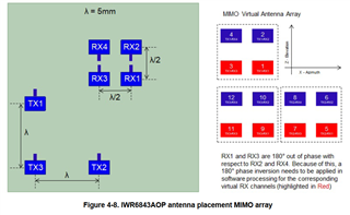
Experiment :
The capture consists of just a few frames.
I pick-up one random frame from the capture (scene is static so all frames should be identical).
I compute all 1D FFTs for each virtual antenna.
I then compute the 2D FFT for each virtual antenna.
2D FFTs are of size (nb_chirps, nb_samples).
Then I try to find the 2D FFT indices corresponding to my strong reflector using detected peak values.
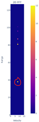
You can see on the above picture a visual representation of the 2D FFTs.
The more antennas are triggered, the more yellow the point is.
Trigger thresholds are high to eliminate noise and low-power relfections.
Negative ranges are not displayed here but range indices goes from 0 to 255 (instead of 0 to +127 on the picture).
Let's say the object is detected at range=r and velocity=v.
Velcoity should be 0 because object is static. Zero velocity is the index 8 in the above picture, which is where we have detected the point, so 
The range (index 89=1.7m, not displayed on the visual but checked in the code) also matches the real distance in the setup scene, so
I then take the value at (r, v) in all 2D FFTs. I have 12 virtual antennas so I have 12 values.
I compute the phase of those values and display them on a 2D grid, according to the virtual antenna pattern illustrated in the 1st picture:
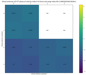
The detected point is static and is facing the radar, so no azimuth nor elevation.
I should expect almost identical values for every phase, but this is not the case.
Supposition:
What I can see is that antennas 1, 2, 3 and 4 have almost same phase each other (small variations are a consequence of imperfect reflection and.also not perfectly centered reflector).
In the same way, antennas 5, 6, 7 and 8 have almost identical phase.
And... antennas 9, 10, 11 and 12 are also almost identical to each other.
The problem appears when we compare phase of virtual antennas that havn't been produced by the same TX antenna.
In fact, if we add ~ 0.35 radians to values coming from TX2 (virtual antennas 5, 6, 7, 8), and ~ 2x0.35=0.7 radians to values coming from TX3 (virtual antennas 9, 10, 11, 12), we have almost identical phases everywhere.
My guess is that some phase shift is added somewhere in the capture process, and this shift seems to be constant between transmitters ( 0 [phase shift] for TX1, 1 [phase shift] for TX2, 2 [phase shift] for TX3).
So my question is: where does this phase shift come from ?
Configuration:
