Because of the Thanksgiving holiday in the U.S., TI E2E™ design support forum responses may be delayed from November 25 through December 2. Thank you for your patience.

This thread has been locked.

If you have a related question, please click the "Ask a related question" button in the top right corner. The newly created question will be automatically linked to this question.

AWR2243: Changing range-angle heatmap scale to a received power scale in dBm (at the RX antenna pins)

Part Number: AWR2243
Other Parts Discussed in Thread: MMWCAS-RF-EVM, MMWCAS-DSP-EVM

Hello,

I am using the TI AWR2243 cascade board with the MMWCAS-RF-EVM (Rev-E) connected to the MMWCAS-DSP-EVM.
mmWave studio software: version 03_00_00_14
Firmware: mmwave_dfp_02_02_02_01

I am using the MATLAB examples for the TDM MIMO modes. My objective is to assign a receive power scale in dBm for the 2D range-angle heatmap, the one generated from "cascade_MIMO_signalProcessing.m". 
I am referring to the received power at the RX antenna pins to analyze the channel path loss.


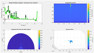
This is how it looks like in the default script. The default heatmap scale is as follows: abs( heatmap ).^(0.4)
After changing the scale of the range-angle heatmap to a dB scale, we get the following scale for the heatmap power. Let's refer to the current power scale by the variable "z" in dB. 
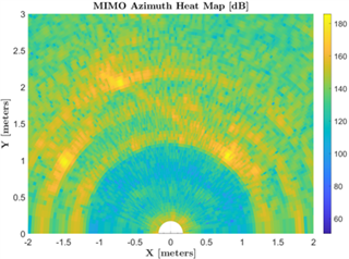
How can I convert the scale of the heatmap above to a received power scale in dBm? 

I think I need help with the link budget in the AWR2243 cascaded kit. My final objective is to display the channel path loss for each object in the heatmap.

  1. I use an RX gain of 50 dB and a TX backoff of 0 dB for all three transmit antennas. What is the TX power at the transmit antenna pins when the TX backoff is 0 dB?
  2. What would be the received power in dBm corresponding to the peak ADC input? Let's refer to the peak power at the ADC input by the variable "x" in dBm.
  3. Do I subtract the RX gain from "x" dBm to get the peak power level at the LNA input? 
  4. Are there any other receiver losses I should account for in the received power calculation at the RX antenna pins in dBm? 
  5. Let's refer to the peak power level at the RX antenna pins by the variable "y" in dBm. What would be the correct way to adjust the heatmap power scale into a received power scale in dBm? Is the following transformation correct? or should it be a different transformation?

    The heatmap received power scale in dBm = the scale "z" in dB plus the variable "y" in dBm?

Thank you for your help!

  • Hi,

         Please see my response inline.

    1. I use an RX gain of 50 dB and a TX backoff of 0 dB for all three transmit antennas. What is the TX power at the transmit antenna pins when the TX backoff is 0 dB?

    With 0db BO the configured TX power is expected at the pins of device. Across temperature and process the absolute max Tx o/p at the pin could be 14dBm.

    2. What would be the received power in dBm corresponding to the peak ADC input? Let's refer to the peak power at the ADC input by the variable "x" in dBm.

    There are RX saturation detectors inside device whcih can be used for monitoring the path. The typical saturation point of the IFA is 1Vpp single-ended, whereas the ADC saturation point is typically around -4dBFs.

    3. Do I subtract the RX gain from "x" dBm to get the peak power level at the LNA input?

    Please refer above.

    4. Are there any other receiver losses I should account for in the received power calculation at the RX antenna pins in dBm.

    Not internal to device, however the PCB traces may contribute to.

    5. Let's refer to the peak power level at the RX antenna pins by the variable "y" in dBm. What would be the correct way to adjust the heatmap power scale into a received power scale in dBm? Is the following transformation correct? or should it be a different transformation. The heatmap received power scale in dBm = the scale "z" in dB plus the variable "y" in dBm?

    Approach seems ok. However, please refer for more details the post processing matlab code file. 

    Regards

  • Hello Abhed Misra,

    Thank you for your replies.
    Please see my follow-up questions inline.


    2.  What would be the received power in dBm corresponding to the peak ADC input? Let's refer to the peak power at the ADC input by the variable "x" in dBm.

    There are RX saturation detectors inside the device which can be used for monitoring the path. The typical saturation point of the IFA is 1Vpp single-ended, whereas the ADC saturation point is typically around -4dBFs.

    3.   Do I subtract the RX gain from "x" dBm to get the peak power level at the LNA input?

    Please refer above.

    Follow-up on the answers of Q2 and Q3:
    I'm still not confident how can I calculate the received power in dBm at the ADC input. Would please correct the following calculation where I'm wrong?

    (a) 2Vpp single-ended corresponds to 10dBm power. 1Vpp single-ended corresponds then to 10 dBm - 6dBm = 4 dBm received power.  Then, the peak received power at the ADC input is -4 dBFs + 4 dBm = 0 dBm maximum received power at the ADC input? is that correct?

    (b) Since the RX gain setting is 50 dB, this means that the peak received power level at the LNA input is 0 dBm - 50 dBm = -50 dBm? is that correct?

    5. Let's refer to the peak power level at the RX antenna pins by the variable "y" in dBm. What would be the correct way to adjust the heatmap power scale into a received power scale in dBm? Is the following transformation correct? or should it be a different transformation. The heatmap received power scale in dBm = the scale "z" in dB plus the variable "y" in dBm?

    The approach seems ok. However, please refer for more details on the post-processing Matlab code file. 

    Follow-up on the answer of Q5:

    Thank you! I checked the post-processing code in MATLAB leading to the heatmap plot. It consists mainly of FFT transform and FFT shift and Windowing in each of the range, Doppler, and azimuth angle domains. I think the windowing choices might contribute to some power losses in the heatmap plot.

    Assume (a) no windowing function is used in any of the three dimensions (range, Doppler, and azimuth angle) and (b) I have to divide the output FFT amplitude by half the input sequence length in every FFT transform operation. Let's refer to the new scale as "z2" in dB.

    does this mean considering -50 dBm as the peak value in the new "z2" scale in dB will produce the received power scale in dBm with acceptable accuracy? or do I need to consider a certain higher "z2" value to be mapped to the -50 dBm? or do I need to think of it from another perspective?


    New question:
    6. For the path loss calculation, do I need to add an antenna gain of 12 dBi to the 14 dBm transmit power to get the effective power after transmission (i.e. EIRP max is 25 dBm)? or is the 12 dBi already included in the 14 dBm (i.e. EIRP max is 14 dBm)?

    Thank you for your help! appreciated.

  • Hi,

             Please refer to the link below for more details on converting the ADC code value to dbm input at the LNA.

    https://e2e.ti.com/support/sensors-group/sensors/f/sensors-forum/613223/awr1243-how-to-calculate-the-precise-power-on-the-tx-and-rx-pin

    Regards