


Other Parts Discussed in Thread: IWR6843
Hi,
I've designed a new board starting from the IWR6843AOPEVM design. The difference between the my board and the IWR6843AOPEVM are:
- there isn't the BREAKAWAY Board section of the IWR6843AOPEVM;:
- the same USB interface (components, signals and interconnection);
- the power section has been modified using a different DC/DC;
- the SOP0,1,2 are managed with the same way using resistors and not jumpers.
Now I'm testing the new board. The voltage levels are all correctly and the interconnection between the PC and the board through USB interface is ok.
When I try to program the flash with your demo I've the problems. The message generated from your program is:
[12/16/2021, 9:51:57 AM] [INFO] Cortex_R4_0: Initialization complete.
[12/16/2021, 9:51:57 AM] [INFO] Cortex_R4_0: Flashing process starting...
[12/16/2021, 9:51:57 AM] [INFO] Cortex_R4_0: Connecting to COM Port /dev/ttyUSB0...
[12/16/2021, 9:51:57 AM] [INFO] Cortex_R4_0: Reset connection to device
[12/16/2021, 9:51:57 AM] [INFO] Cortex_R4_0: Set break signal
[12/16/2021, 9:52:17 AM] [ERROR] Cortex_R4_0: Initial response from the device was not received. Please power cycle device before re-flashing.
[12/16/2021, 9:52:19 AM] [ERROR] Cortex_R4_0: Not able to connect to serial port. Recheck COM port selected and/or permissions.
[12/16/2021, 9:52:19 AM] [INFO] Cortex_R4_0: Flashing instance clean-up initiated...
[12/16/2021, 9:52:19 AM] [INFO] Cortex_R4_0: Instance deinitialized!
I've also measred the SOP0,1,2 levels and they are the same levels that I've measued in the IWR6843AOPEVM.
I've also matched the messages exchange through the serial lines USB_AR_RS232TX,USB_AR_RS232RX of my board and the IWR6843AOPEVM, during the configuration of the flash.
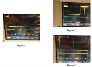
At the start up, when the configuration operation is executed from the PC the USB_AR_RS232RX (yellow line) go down and the IWR6843 answers with a message on the USB_AR_RS232TX line
(blue line): see the figure 1. The identical behaviour has been observed with my board and the IWR6843AOPEVM.
Then this first step, I've observed a difference between the two boards:
- Figure 2. in the case of IWR6843AOPEVM, the line USB_AR_RS232RX (yellow line) go high after 100 ms and start the programming activity.
- Figure 3. In the case of my board, the line USB_AR_RS232RX (yellow line) is always low and the PC program generates the error message and stops the programming activity:
[12/16/2021, 9:52:17 AM] [ERROR] Cortex_R4_0: Initial response from the device was not received. Please power cycle device before re-flashing.
[12/16/2021, 9:52:19 AM] [ERROR] Cortex_R4_0: Not able to connect to serial port. Recheck COM port selected and/or permissions.
Surely, the Flash of the IWR6843AOPEVM is configured and the flash in the my board are clear.
Why there is this difference? Could you help me to understand this problem and stop my activity?
Best Regards,
Daniele Sassaroli
