This thread has been locked.

If you have a related question, please click the "Ask a related question" button in the top right corner. The newly created question will be automatically linked to this question.

AWR2944EVM: The questions about the DDMA scheme

Part Number: AWR2944EVM

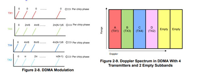
Hi, In the doc "High-End Corner Radar Reference Design",the DDMA scheme is descriped as belows in the page 8:

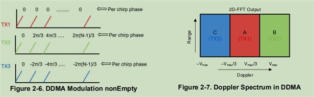
but in the ../mmwave_mcuplus_sdk_04_02_00_01/ti/datapath/dpc/objectdetection/objdethwaDDMA/docs/doxygen/html/index.html,the DDMA is as below:

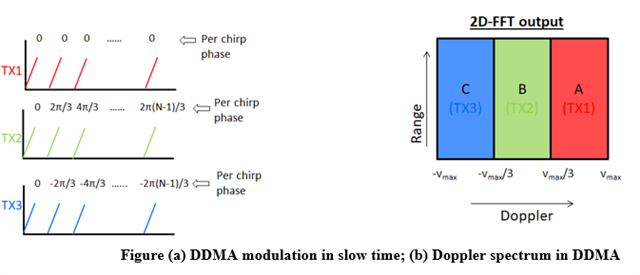
In the two picture, the DDMA modulation is  identical,but the doppler spectrumn is different,which one is right?And why?

BR,

Rata

  • Hi,

    There will be some delays in answering this question.

    We will get back to you be end of next week

    thank you

    Cesar

  • Hi Rata,

    Apologies for the delay; I was on vacation last week.

    The doxygen documentation captures the essence of the DDMA scheme, but the TX antenna ordering in the doppler spectrum is not correct in the diagrams. The High End Corner Radar Reference Design (link) has the updated diagram, which contains the true depiction of the modulation and corresponding doppler spectrum for the lab (this is also true for the OOB demo):

    Note that the high end corner radar lab uses 4TX and 2 empty sub-band modulation scheme.

    The reason we order the doppler spectrum as TX1-TX3-TX4-TX2 and not simply TX1-TX2-TX3-TX4 is that TX 1,3,4 are the azimuth antennae. Keeping them contiguous in the doppler spectrum makes implementing the corresponding EDMA transfers and FFT's easier for the azimuth FFT.

    Regards,

    Aayush

  • Hi Aayush,

      Thanks for your reply. I still have a question, in the figure 2-9, what are the velocity scopes that the spectrum A,B,C,D and empty bands describe? The spectrum A represents 0~Vmax/3, B representsVmax/3~2Vmax/3 ,is that right?

    BR

    Rata

  • Hi Rata,

    I have a general conception of this, but want to confirm my understanding with my colleagues. I will come back to you tomorrow on this topic.

    Regards,

    Aayush

  • Hi Rata,

    In general, as you go from bin 0 to bin max in doppler, velocity goes from 0 to Vmax, then -Vmax, then back to 0, i.e: [0->Vmax]+[-Vmax->0). The same would apply to the DDMA doppler spectrum also.

    The ordering shown above is the ordering when the velocity is within 0 to Vmax/6. Figure 2-10 shows how this ordering changes as the velocity of objects increase:

    Regards,

    Aayush

  • Hi Aayush,

       Thanks for your reply.As you said,"The ordering shown above is the ordering when the velocity is within 0 to Vmax/6. Figure 2-10 shows how this ordering changes as the velocity of objects increase:" ,does "The ordering shown above" mean the Figure 2-9?

       In the figure you provide,  Hopothesis 1 represents the velocity within 0 to Vmax/6 or  -Vmax/6  to Vmax/6, which one is right? Can you provide any theoretical basis for that ? There are other Hopothesises ,Hopothesis 2~Hopothesis 6. What  do those represent for?

       I still have another question, whether the location of  TX1  represents the velocity scope of  the object because that the chirp phase of the TX1 is 0?

     BR

    Rata

  • Hi Rata,

    Yes, by the figure above I meant figure 2-9 (above as in my previous reply).

    Please let me get back to you in a day or two about the rest of your questions.

    Regards,

    Aayush