


Other Parts Discussed in Thread: AWR2243, , MMWCAS-DSP-EVM, TIDEP-01012
Hi TI,
I am currently using the MMWCAS-RF-EVM (AWR2243 SOC) with the MMWCAS-DSP-EVM. I am currently running the cascade_configuration_MIMO lua script. I do have several questions with regards to the chirp parameters.
My intent is to use it for the measurement of some Corner Reflectors around 20m, possibly 30m both static, and in moving scenarios (radar static target moving; radar moving, target static; radar moving, target moving).
I have referred to the programming chirp parameters in TI Radar Devices pdf guide as well as the Imaging Radar using cascaded mmWave Sensor Reference Design (TIDEP-01012), and decided on the following table
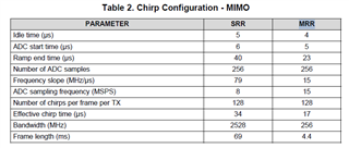
I've attached the parameter portion of the lua script below (taking MRR in table 2 as a reference),
-- Profile configuration
local profile_indx              =   0
local start_freq                =   77     -- GHz
local slope                     =   15     -- MHz/us
local idle_time                 =   4      -- us
local adc_start_time            =   5      -- us
local adc_samples               =   256    -- Number of samples per chirp
local sample_freq               =   15000   -- ksps
local ramp_end_time             =   23     -- us
local rx_gain                   =   48     -- dB
local tx0OutPowerBackoffCode    =   0
local tx1OutPowerBackoffCode    =   0
local tx2OutPowerBackoffCode    =   0
local tx0PhaseShifter           =   0
local tx1PhaseShifter           =   0
local tx2PhaseShifter           =   0
local txStartTimeUSec           =   0
local hpfCornerFreq1            =   0      -- 0: 175KHz, 1: 235KHz, 2: 350KHz, 3: 700KHz
local hpfCornerFreq2            =   0      -- 0: 350KHz, 1: 700KHz, 2: 1.4MHz, 3: 2.8MHz

-- Frame configuration
local start_chirp_tx            =   0
local end_chirp_tx              =   11
local nchirp_loops              =   128     -- Number of chirps per frame
local nframes_master            =   10     -- Number of Frames for Master
local nframes_slave             =   10     -- Number of Frames for Slaves
local Inter_Frame_Interval      =   100    -- ms
local trigger_delay             =   0      -- us
local trig_list                 =   {1,2,2,2} -- 1: Software trigger, 2: Hardware trigger
However can i kindly ask the following.
1. for the frame configuration, would 10 frames suffice for both master and slave? and how should i configure the Inter_Frame_interval parameter? as of right now it is 100ms.
2. What does the local rx_gain (line 10) do in the profile configuration
3. for the case whereby the target is moving and the radar is stationary, running a single instance of cascade_ capture definately would not suffice. Instead would you recomend running the system in infinite framing mode? OR increase the num_loops parameter (line 20) in Cascade_capture.lua shown below: I want to be able to show the radar picking up the movement of the targets similar to this TI video
--[[
    A. FRAMING & CAPTURE
    1. Triggering Slave (3, 2, 1) sequentially in a hardware triggered mode.
    2. Triggering Master in a software triggered mode.

    B. TRANSFERRING FILES
    1. The data is stored in file(s) with max cap placed at 2 GB.
    2. The files can be retrieved from the SSD (/mnt/ssd folder) using WinSCP.

Note: Update lines 18 to 49 as needed before using this script.
--

Note: "capture_time"  is a timeout for this script alone to exit - it does not control the
actual duration of capture. The actual capture duration depends on the configured frame time
and number of frames.
--]]

capture_time                     =   2000                             -- ms
inter_loop_time                  =   2000                             -- ms
num_loops                        =   1                               --original is 1

--[[
Note: Change the following three parameters as desired:
1. n_files_allocation: is the number of files to preallocate on the SSD.
   This improves capture reliability by not having frame drops while switching files.
   The tradeoff is that each file is a fixed 2047 MB even if a smaller number of frames are captured.
   Pre-allocate as many files as needed based on (size_per_frame * number_of_frames) to be captured.
2. data_packaging: select whether to use 16-bit ADC data as is, or drop 4 lsbits and save 4*12-bit numbers in a packed form
   This allows a higher frame rate to be achieved, at the expense of some post-processing to unpack the data later.
   (Matlab should still be able to unpack the data using the '*ubit12' argument to fread instead of 'uint16')
   The default is no-packing, for simplicity
3. capture_directory: is the filename under which captures are stored on the SSD
   and is also the directory to which files will be transferred back to the host
   The captures are copied to the PostProc folder within mmWave Studio

   Note: If this script is called multiple times without changing the directory name, then all
         captured files will be in the same directory with filename suffixes incremented automatically.
         It may be hard to know which captured files correspond to which run of the script.
   Note: It is strongly recommended to change this directory name between captures.
--]]

n_files_allocation              =   0
data_packaging                  =   0                       -- 0: 16-bit, 1: 12-bit
capture_directory               =   "test_data_MIMO_1.2ghz_USRR"
num_frames_to_capture           =   0                       -- 0: default case; Any positive value - number of frames to capture

framing_type                    =   1                       -- 0: infinite, 1: finite
stop_frame_mode                 =   0                       -- 0: Frame boundary, 2: Sub-frame boundary,
                                                            -- 3: Burst boundary, 4: HW/Sub-frame triggered
Thank You,
Your help is much appreciated!
