


Ensure both FEMM and the Magnetic Sensing Proximity Tool are downloaded to conduct magnetic simulations using the tool.
See this E2E FAQ for download of the Magnetic Sensing Proximity Tool: Tool FAQ
FEMM can be downloaded from the link included here: FEMM Download
For the first example, we will emulate a mechanical head-on sensing movement similar to what can be found in magnetic two-state switches. Advantages of this implementation include small size, wide selection of suitable devices, and contactless position sensing. The use of a unipolar switch enables the system to be cost efficient, with the device sensitivity dictating the operating points of the hall switch.
For the test, we will implement a south facing block magnet moving head-on towards a unipolar switch. The magnet is a N35 cube with 5mm dimensions for length, width, and thickness. The displacement dimensions range from 10mm(d1) to 30mm(d2) with no X or Y offset referenced to the center of the package. The TMAG5124A unipolar switch in SOT-23 package will be used for the simulations. Figure 1 displays the input configuration for the simulation. Enter desired configuration settings into the tool, and generate results for the simulation by selecting “Calculate B-Field & Vout”. Note, any simulation involving a block magnet will not utilize FEMM for the B-Field calculation. Therefore, it is possible to conduct this specific test with only the Magnetic Sensing Proximity Tool installed.
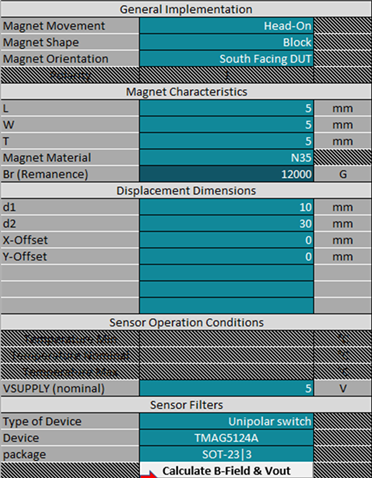
Figure 1: Head-On Magnet Implementation
Figure 2 demonstrates the physical movement used for the head-on simulation
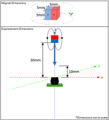
Figure 2: Simulation Movement Representation
Figure 3 represents the sensor output and B-Field(X,Y,Z) plotted with respect to magnet position.
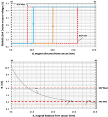
Figure 3: Head-On Output Results
The output waveform demonstrates typical switching behavior at 19.9mm for a low to high transition, and 15.1mm for high to low.
For additional information on developing a two-state switch, see this application brief covering the topic: Two-State Selector Using Hall-Effect Sensors
For additional information on using a head-on sensing movement, see this application brief covering the topic: Head-on Linear Displacement Sensing Using Hall-Effect Sensors
Next FAQ, Part Two: Simulating slide-by movement with a ratiometric PWM Hall-Effect sensor
