Hello
We are designing the ultrasonic flow meter on the TI chipset and struggling with Zero-flow-offsets issues.
Section 6.1.2 Improving Zero-flow-offset and Offset Drift Over Temperature of the https://www.ti.com/lit/an/snia020/snia020.pdf app note seems to be helpful in this regard.
It says: "The electrical impedance of the path can be controlled using an impedance matching solution, based on the principal of electroacoustic reciprocity. A well implemented impedance matching feature results in the operation of the circuit in a "sufficiently reciprocal" way".
Well, cool, electroacoustic reciprocity it's what we need for sure need....
But then I see the schematics being offered on page 9, and all it is is basically a 300 pf capacitor in transmit mode parallel to the piezo (see the pic below). And also a 200 Ohm resistor is shunting the receiving piezo, which seems to be just damping the "ringing" (and the useful signal as well).

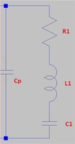
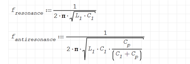
Looking at the equivalent schematics of the piezo and it's resonance and anti-resonance formulas it looks like it's resonance is defined just by L1 and C1, and not by parallel capacitor (which affects anti-resonance only). So adding extra 300pf at transmit mode will likely not change resonant frequency and piezo's behavior while transmitting.


In conclusion, I am wondering how the proposed solution can help with the electroacoustic reciprocity and how exactly this proposed matching works.
Thank you for your time,
Dmitry

