This thread has been locked.

If you have a related question, please click the "Ask a related question" button in the top right corner. The newly created question will be automatically linked to this question.

AWR1243: AWR Tx'es don't turn on

Part Number: AWR1243
Other Parts Discussed in Thread: TDA2

Hi, TI experts!

We have two custom cascade boards (AWR1243) . One is fully operational (reference board) but the other doesn't run Tx'es in my viewpoint.

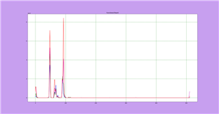
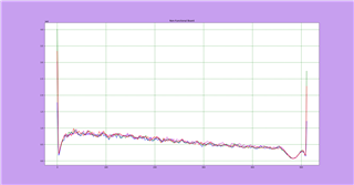
Here are the R-profiles from operational board and nonfunctional for the same scene (frame configurations are same too). Second one looks like Tx'es are not run. But power consumption is equal for both boards.


We've seen that 20 GHz SYNC signal level is a little bit less for the non-functional board.

Can you suggest a possibble reason for such operating? Is there any AWR mode while there is a power consumption but there is no radiation?

Thank you

Timur Suanov

  • A little update.

    We've run monitoring functions, got the attached report.

    =======================================================
    -------------------------(0)-------------------------
     AR12XX: MON: Temperature Report Status = 31
     AR12XX: MON: Error Code = 0x0
     AR12XX: MON: TEMP_RX0 = 47 deg C
     AR12XX: MON: TEMP_RX1 = 47 deg C
     AR12XX: MON: TEMP_RX2 = 47 deg C
     AR12XX: MON: TEMP_RX3 = 47 deg C
     AR12XX: MON: TEMP_TX0 = 48 deg C
     AR12XX: MON: TEMP_TX1 = 48 deg C
     AR12XX: MON: TEMP_TX2 = 49 deg C
     AR12XX: MON: TEMP_PM = 47 deg C
     AR12XX: MON: TEMP_DIG1 = 46 deg C
     AR12XX: MON: Time Stamp = 59267 ms
    =======================================================
    -------------------------(0)-------------------------
     AR12XX: MON: RX Gain Phase Report Status = 0
     AR12XX: MON: Error Code = 0x0
     AR12XX: MON: Profile Index = 0
     AR12XX: MON: Rx Gain [0] = 266
     AR12XX: MON: Rx Phase [0] = 64868
     AR12XX: MON: Rx Gain [1] = 260
     AR12XX: MON: Rx Phase [1] = 63236
     AR12XX: MON: Rx Gain [2] = 265
     AR12XX: MON: Rx Phase [2] = 62198
     AR12XX: MON: Rx Gain [3] = 260
     AR12XX: MON: Rx Phase [3] = 32
     AR12XX: MON: Rx Gain [4] = 281
     AR12XX: MON: Rx Phase [4] = 4194
     AR12XX: MON: Rx Gain [5] = 279
     AR12XX: MON: Rx Phase [5] = 3026
     AR12XX: MON: Rx Gain [6] = 285
     AR12XX: MON: Rx Phase [6] = 2432
     AR12XX: MON: Rx Gain [7] = 268
     AR12XX: MON: Rx Phase [7] = 4148
     AR12XX: MON: Rx Gain [8] = 301
     AR12XX: MON: Rx Phase [8] = 12210
     AR12XX: MON: Rx Gain [9] = 300
     AR12XX: MON: Rx Phase [9] = 10872
     AR12XX: MON: Rx Gain [10] = 306
     AR12XX: MON: Rx Phase [10] = 10422
     AR12XX: MON: Rx Gain [11] = 291
     AR12XX: MON: Rx Phase [11] = 11016
     AR12XX: MON: Time Stamp = 59270 ms
    =======================================================
    -------------------------(0)-------------------------
     AR12XX: MON: RX Noise Figure Report Status = 0
     AR12XX: MON: Error Code = 0x0
     AR12XX: MON: Profile Index = 0
     AR12XX: MON: Noise Figure Value [0] = 219
     AR12XX: MON: Noise Figure Value [1] = 222
     AR12XX: MON: Noise Figure Value [2] = 219
     AR12XX: MON: Noise Figure Value [3] = 229
     AR12XX: MON: Noise Figure Value [4] = 199
     AR12XX: MON: Noise Figure Value [5] = 208
     AR12XX: MON: Noise Figure Value [6] = 196
     AR12XX: MON: Noise Figure Value [7] = 218
     AR12XX: MON: Noise Figure Value [8] = 180
     AR12XX: MON: Noise Figure Value [9] = 183
     AR12XX: MON: Noise Figure Value [10] = 171
     AR12XX: MON: Noise Figure Value [11] = 194
     AR12XX: MON: Time Stamp = 59271 ms
    =======================================================
    -------------------------(0)-------------------------
     AR12XX: MON: RX IF Stage Report Status = 7
     AR12XX: MON: Error Code = 0x0
     AR12XX: MON: Profile Index = 0
     AR12XX: MON: HPF Cutoff Error [0] = 4
     AR12XX: MON: LPF Cutoff Error [0] = 8
     AR12XX: MON: RX IFA Gain Error [0] = 243
     AR12XX: MON: HPF Cutoff Error [1] = 3
     AR12XX: MON: LPF Cutoff Error [1] = 6
     AR12XX: MON: RX IFA Gain Error [1] = 245
     AR12XX: MON: HPF Cutoff Error [2] = 4
     AR12XX: MON: LPF Cutoff Error [2] = 253
     AR12XX: MON: RX IFA Gain Error [2] = 247
     AR12XX: MON: HPF Cutoff Error [3] = 2
     AR12XX: MON: LPF Cutoff Error [3] = 4
     AR12XX: MON: RX IFA Gain Error [3] = 250
     AR12XX: MON: HPF Cutoff Error [4] = 3
     AR12XX: MON: LPF Cutoff Error [4] = 7
     AR12XX: MON: RX IFA Gain Error [4] = 245
     AR12XX: MON: HPF Cutoff Error [5] = 6
     AR12XX: MON: LPF Cutoff Error [5] = 11
     AR12XX: MON: RX IFA Gain Error [5] = 245
     AR12XX: MON: HPF Cutoff Error [6] = 2
     AR12XX: MON: LPF Cutoff Error [6] = 3
     AR12XX: MON: RX IFA Gain Error [6] = 246
     AR12XX: MON: HPF Cutoff Error [7] = 5
     AR12XX: MON: LPF Cutoff Error [7] = 249
     AR12XX: MON: RX IFA Gain Error [7] = 250
     AR12XX: MON: Time Stamp = 59272 ms
    =======================================================
    -------------------------(0)-------------------------
     AR12XX: MON: Tx0 Power Report Status = 3
     AR12XX: MON: Error Code = 0x0
     AR12XX: MON: Profile Index = 0
     AR12XX: MON: TX Power Value [0] = 121
     AR12XX: MON: TX Power Value [1] = 124
     AR12XX: MON: TX Power Value [2] = 124
     AR12XX: MON: Time Stamp = 59272 ms
    =======================================================
    =======================================================
    -------------------------(0)-------------------------
     AR12XX: MON: Tx0 Ball Break Report Status = 1
     AR12XX: MON: Error Code = 0x0
     AR12XX: MON: TX reflection coefficient = -163
     AR12XX: MON: Time Stamp = 59272 ms
    =======================================================
    =======================================================
     AR12XX: MON: Monitorring Report Header, Temp = 47
    =======================================================
    -------------------------(0)-------------------------
     AR12XX: MON: Tx Gain Mismatch Report Status = 0
     AR12XX: MON: Error Code = 0x0
     AR12XX: MON: Profile Index = 0
     AR12XX: MON: TX Gain Value [0] = -140
     AR12XX: MON: TX Phase Value [0] = 52528
     AR12XX: MON: TX Gain Value [1] = 0
     AR12XX: MON: TX Phase Value [1] = 0
     AR12XX: MON: TX Gain Value [2] = 0
     AR12XX: MON: TX Phase Value [2] = 0
     AR12XX: MON: TX Gain Value [3] = -139
     AR12XX: MON: TX Phase Value [3] = 43497
     AR12XX: MON: TX Gain Value [4] = 0
     AR12XX: MON: TX Phase Value [4] = 0
     AR12XX: MON: TX Gain Value [5] = 0
     AR12XX: MON: TX Phase Value [5] = 0
     AR12XX: MON: TX Gain Value [6] = -104
     AR12XX: MON: TX Phase Value [6] = 36293
     AR12XX: MON: TX Gain Value [7] = 0
     AR12XX: MON: TX Phase Value [7] = 0
     AR12XX: MON: TX Gain Value [8] = 0
     AR12XX: MON: TX Phase Value [8] = 0
     AR12XX: MON: Time Stamp = 59273 ms
    =======================================================
    -------------------------(0)-------------------------
     AR12XX: MON: Tx0 BPM Report Status = 3
     AR12XX: MON: Error Code = 0x0
     AR12XX: MON: Profile Index = 0
     AR12XX: MON: TX output amplitude difference = 0
     AR12XX: MON: Time Stamp = 59274 ms
    =======================================================
    =======================================================
    -------------------------(0)-------------------------
     AR12XX: MON: Synthesizer Frequency Report Status = 1
     AR12XX: MON: Error Code = 0x0
     AR12XX: MON: Profile Index = 0
     AR12XX: MON: Maximum instantaneous frequency error = -5773
     AR12XX: MON: Frequency error threshold violation = 0
     AR12XX: MON: Time Stamp = 89255 ms
    =======================================================
    -------------------------(0)-------------------------
     AR12XX: MON: Tx External Analog Signal Report Status = 0
     AR12XX: MON: Error Code = 0x0
     AR12XX: MON: External Measured Value [0] = 0
     AR12XX: MON: External Measured Value [1] = 0
     AR12XX: MON: External Measured Value [2] = 0
     AR12XX: MON: External Measured Value [3] = 0
     AR12XX: MON: External Measured Value [4] = 0
     AR12XX: MON: External Measured Value [5] = 0
     AR12XX: MON: Time Stamp = 59274 ms
    =======================================================
    -------------------------(0)-------------------------
     AR12XX: MON: Tx0 Internal Analog Signal Report Status = 2
     AR12XX: MON: Error Code = 0x0
     AR12XX: MON: Profile Index = 0
     AR12XX: MON: Time Stamp = 59274 ms
    =======================================================
    =======================================================
    -------------------------(0)-------------------------
     AR12XX: MON: Rx Internal Analog Signal Report Status = 4095
     AR12XX: MON: Error Code = 0x0
     AR12XX: MON: Profile Index = 0
     AR12XX: MON: Time Stamp = 59275 ms
    =======================================================
    -------------------------(0)-------------------------
     AR12XX: MON: PMCLKLO Internal Analog Signal Report Status = 3
     AR12XX: MON: Error Code = 0x0
     AR12XX: MON: Profile Index = 0
     AR12XX: MON: Time Stamp = 59276 ms
    =======================================================
    -------------------------(0)-------------------------
     AR12XX: MON: GPADC Internal Analog Signal Report Status = 3
     AR12XX: MON: Error Code = 0x0
     AR12XX: MON: GP ADC Reference 1 Value = 254
     AR12XX: MON: GP ADC Reference 2 Value = 672
     AR12XX: MON: Time Stamp = 59276 ms
    =======================================================
    -------------------------(0)-------------------------
     AR12XX: MON: PLL Control Voltage Report Status = 127
     AR12XX: MON: Error Code = 0x0
     AR12XX: MON: External Measured Value [0] = 506
     AR12XX: MON: External Measured Value [1] = 1232
     AR12XX: MON: External Measured Value [2] = 239
     AR12XX: MON: External Measured Value [3] = 2014
     AR12XX: MON: External Measured Value [4] = 1253
     AR12XX: MON: External Measured Value [5] = 251
     AR12XX: MON: External Measured Value [6] = 3992
     AR12XX: MON: External Measured Value [7] = 0
     AR12XX: MON: Time Stamp = 59276 ms
    =======================================================
    -------------------------(0)-------------------------
     AR12XX: MON: PLL Control Voltage Report Status = 63
     AR12XX: MON: Error Code = 0x0
     AR12XX: MON: External Measured Value [0] = 5998
     AR12XX: MON: External Measured Value [1] = 1999
     AR12XX: MON: External Measured Value [2] = 1000
     AR12XX: MON: External Measured Value [3] = 100
     AR12XX: MON: External Measured Value [4] = 104
     AR12XX: MON: External Measured Value [5] = 999
     AR12XX: MON: External Measured Value [6] = 0
     AR12XX: MON: External Measured Value [7] = 0
     AR12XX: MON: Time Stamp = 59276 ms

    Regards

    Timur

  • Hi,

         Couple of questions:

    1. Has these boards design been tested before?

    2. Was the design being reviewed by TI representative?

    3. Are you using mmWave studio or running a script or application code on your host?

    The power consumption is indicative of configuration of device, however there can be several reasons for signal/spectrum invisible. There could be TX ball soldering issue, Antenna layout issue, etc. 

    Regards

  • Hi, Abhed! Thank for quick reply.

    1) Yes, this design have been tested, we have reference boards (same design) fully operational. There is one difference - PCB manufacturer.

    2) No, design haven't been reviewed by TI representative.

    3) We use application code on the host (it is embeded TDA2).

    We've got monitor reports for functional board and broken one. There is the only difference: please refer string 165

       AR12XX: MON: Tx0 Internal Analog Signal Report Status = 2 (broken board)

       AR12XX: MON: Tx0 Internal Analog Signal Report Status = 3 (functional board)

    From documentation:

    STATUS_SUPPLY_TXn         1 (functional board)               0 (broken board)
    STATUS_PWRDET_TXn       1 (functional board)               1 (broken board)

    But it isn't clear from documentation what does mean STATUS_SUPPLY_TXn  FAIL.  Can you clarify this please?

    I asumme there is no soldering issue, we have resoldered one chip (it was soldered nicely), moreover in cascade config no one of 12 Tx'es runs on broken board, while any one runs on other four boards we made. Antenna and waveguide layouts (stackup and patch) are the same as in TI reference cascade design, farther we would capture at the least a poor signal due to antenna mismatch not such a full zero. I guess AWR chip doesn't supply power to Tx for some reason.

    The only difference between functional and broken boards - is manufacturer, but everything looks good (in TEST SOURCE mode we capture data) exept the Tx radiation.

    Regards

    Timur

  • Hi,

          Manufacturer is a VERY critical piece and a lot (material/process/tolerance/etching...) depends on it. This may be a broken piece. I would recommend to look at the https://www.ti.com/lit/pdf/spracg5, especially section 2.3. 

    The monitor API response details can be looked in to ICD(in DFP). The reported values from broken board report PS DAC failure. This is unexpected. 

    The comparison you did is good way of debugging the problem. I would also suggest to use the working board and generate CW tone and grab it on broken board to ascertain RX side too.

    Test Source is the internal loopback and hence does not ascertain the typical board layout RF performance.

    Regards

  • We use mmwave_dfp_01_02_00_00, so I guess this monitoring status is 2 bit, like this

    This statuses I've taken from DFP doxygen. Thanks for idea with CW tone, we'll try it.

    Thank you

    Timur

  • Hi,

           Apologies I missed you are working on AWR1243.

    Apart from CW test please have a comparison of monitoring reports also done.

    Regards

  • Hi, Abdeh.

    We've done tests - Rxes are fine.

    Sorry, I don't understand about monitoring reports - we already made the comparison for functional and broken boards, I've wrote above the only difference:

    STATUS_SUPPLY_TXn         1 (functional board)               0 (broken board)
    STATUS_PWRDET_TXn       1 (functional board)               1 (broken board)    
    // in Interface Control Document  there is "STATUS_DCBIAS" instead of "STATUS_PWRDET_TXn".

    Can you, please, explain STATUS_SUPPLY_TXn parameter?

    Additional info on this matter:
    1) We've run board in a single chip mode and it operates correctly (both internal LO and looped back LO).

    2) In cascade mode with single chip in master mode with looped back LO no one Tx runs.

    3) Two chips in cascade recieve no signal too, picture is the same as for four chips.

    Guess the reason is in low power 20 GHz SYNC, doesn't it? Also please confirm that in single chip mode AWR is forced to use internal LO regardless of configuration parameters.

    Thank you

    Timur

  • Hi,

      Good to know that.

    1. How did you confirm the RXs are fine? Did you generate a CW TX tone and RX it n broken board? Did you operate the device in single chip mode during this?

    2. When you say you operate the device in single chip mode did you only check primary or secondary device also? Were both working OK?

    Regards

  • Hi,

    1. We don't run CW mode, it not longer needed as we've recieved data completely coresponding to scene in single chip mode at any Rx while any Tx runs.

    2. We've only check primary device in single chip mode.

    But now I've update. PCB-manufacturer did not make a backdrill of vias on 20 GHz SYNC, we have backdrilled it on our own, and now all devices in cascade work properly.

    Thank you for your assistance!

    Regards

    Timur