This thread has been locked.

If you have a related question, please click the "Ask a related question" button in the top right corner. The newly created question will be automatically linked to this question.

IWR6843AOP: SPI transfer calls an error when it encounters a Semaphore

Part Number: IWR6843AOP
Other Parts Discussed in Thread: MMWAVEICBOOST

Hello,

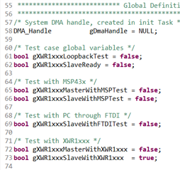
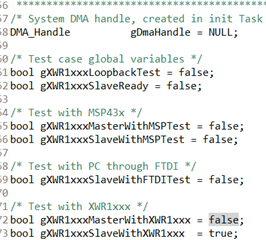
I'm working on updating the out of box demo to enable SPI for industrial toolbox 4_10_0 and SDK  3_05.
The point of this is to get information on the range doppler map. UART isn't fast enough (project needs at least 1MHz) and doesn't provide sufficient frame rate to interpret information.
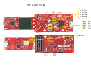
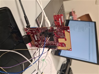
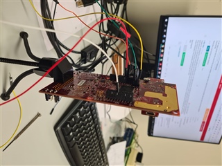
The IWR6843aop is configured as a slave with a raspberry pi as SPI master.

When I run the pi code, I only receive 255 as output instead of the sent 0x55.
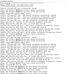
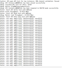
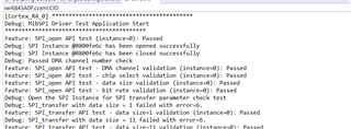
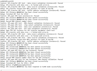
My latest update trace when debugging is attached below:

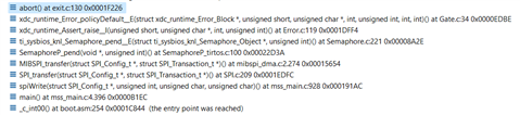
The chip returns an error when it gets to the semaphore pend with SPI_MODE_BLOCKING. My initial theory was that there was a different task blocking the SPI and both the SPI and that mystery task had the same level of priority

But then again, to try and confirm that theory, I took the spiWrite function out of my dedicated tasks (so other parts of the demo transmitted over UART) and called spiWrite early in my main function

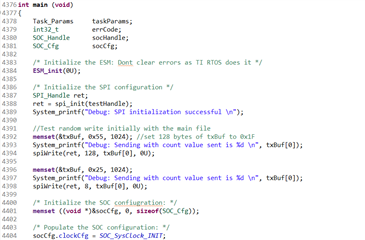
This did not work and I got the same debug trace attached earlier.

If anyone has faced a similar problem, could you please explain how you solved it?
Or if you have an idea on how to approach this, your help will be greatly appreciated. 

Thank you

  • Hi,

    I would recommend that you take a look at the SPI driver test code that can be found under <mmwave_sdk_loc>/packages/ti/drivers/spi/test

    In addition to what I can see in your screenshot, you will need to at least complete the pinmux configuration and include a SPI_open call. Take a look at the SPI driver test code, and let me know if you have any questions, it should provide a good reference on what you are trying to accomplish.

    Best Regards,
    Alec

  • Hello Alec,

    A lot of my code was based on the test code available in the drivers.

    My spi_init function is attached below

    My spiWrite function is also attached below:

    While debugging, I noticed everything remains normal and the correct data is held in each variable.

    The debug crashes when I reach this segment of the code (attached below):

    A more detailed debug trace is this

    That's the error I have not figured out yet. 

    Thank you

  • Hi,

    My apologies, I did not realize you had made a custom Init function. Have you successfully ran the SPI test on your setup? This may help to ensure there are no configuration issues on the device. You should also be able to use this to validate any existing HW connections you have.

    Best Regards,
    Alec

  • Hi Allec,

    Unfortunately, I have not been able to run the SPI test. I could not find relevant instructions on testing the drivers.

    Could you please point me to the necessary guidelines or resources for testing out the drivers? If there are none, could you please give a step by step instruction on how to do this?

    Thanks!

  • I found some instructions here -C:/ti/mmwave_sdk_03_05_00_04/docs/mmwave_sdk_unit_test_procedure.pdf
    Hoping that gives me further clarity.

  • Hello Alec,

    I tried today to run the SPI test with 2 identical devices, 1 configured as Master, the other Slave.

    Based on the results, It seems there is something inherently wrong with the slave setup.
    The Master outputted this consistently:

    The receive message should be 0x3456 i.e the MAGIC NUMBER.
    While the master outputs this, the slave seems to get stuck in an infinite IDLE mode.

    It outputs this:

    The slave stays there until the master is disconnected. About a minute after master disconnection, it responds with this:

    On face value, it seemed initially to be some synchronization issue so I checked the output clock of the master with an oscilloscope, but that remained normal with 1MHz. The slave select pin was also consistently held high.

    The project I'm working on requires the iwr to be in slave mode with a raspberry pi as master. How do you suggest this error could be fixed?

    Thank you.

  • Hi,

    Could you provide photos of your hardware setup, including ones that show the various switch/mux settings on the boards?

    Best Regards,
    Alec

  • Hi Alec,

    I can not get images across to you immediately as we dismantled our setup for the time being. But here's a description of what that looks like.

    1. After flashing the both sensors (IWR6843AOP EVMs) with the cssdebug image, we ensured to put them in the boost mode according to image below:

    2. The sensor are then placed on the MMWAVEICBOOST board which with the MUX for BP/LP mode (4th row) according to following image too:

    3. Using the guide from the boostcard pamphlet, we made connections for SPI pins at the jumper headers at the back of the boostcards:

    SPI-MOSI: J6:12

    SPI-MISO: J6:14

    SPI-CS: J6:6

    SPI-CLK: J5:13

    GND: J5:4

    Here also, the SPO was set at 001 according to:

    4. We were certain that the wires fit the jumper headers, and were able to detect the clock as earlier reported. Also, out software compiled successfully.

    What else could we have been missing?

  • Thanks for clarifying that, all those settings should be correct. Let's take a step back, and take your code and set the SPI slave to the default params (just comment out the specific params you set) and lets test to see what the behavior is there. The SPI driver is used by many other customers, so there must be something in the configuration/implementation here that we are not noticing. If it still errors with the default params, post any debug output information that it provides and we can go from there

    Best Regards,
    Alec

  • Hello Alec, I wanted to try a new approach today.

    The plan is to try and set up a spi connection between the msp432e401yt and the iwr6843aop.
    To do this, I'm following the level sense demo found here but with a few modifications.

    In this demo's presentation files, it illustrates how to flash the msp432 using CCS.
    So, install the SDK and add in CCS, plug in via USB and try to debug (which also loads the file) using a .ccxml fie.

    I did all this but once I try to load the .out file of the msp432 in the level sense, I receive this : 

    CORTEX_M4_0: GEL Output:
    Memory Map Initialization Complete
    CORTEX_M4_0: Can't Run Target CPU: (Error -1268 @ 0x1090001) Device is locked up in Hard Fault or in NMI. Reset the device, and retry the operation. If error persists, confirm configuration, power-cycle the board, and/or try more reliable JTAG settings (e.g. lower TCLK). (Emulation package 9.6.0.00172)

    I should add that this is a brand new msp432 I'm using.

    I tried reading the user guide to see if there was anything I had to do (eg removing jumpers) for 1st time use but nothing is explicitly stated.

    Do you perhaps have an idea what  could be done to rectify the situation?

    Thank you.

  • Hi,

    Okay, so there's a bit to process here. I cannot offer too much comment on what is happening with the MSP432 (since this forum is for radar sensors) but there are a few general things we can look at. Can you verify that the MSP432 module is installed in your CCS? It is easy to forget to add it if you do not do it during installation. It may also be worth reinstalling CCS, because if you're having issue with multiple devices, I wonder if something in your installation has become corrupted.

    Take a look at your CCS install and let's go from there.

    Best Regards,
    Alec

  • Hello Alec,

    I was able to connect both EVMs in their respective states with the default parameters from the SPI test.

    Debug information from the master device is shown:

    Debug information from the slave is attached below:

    For completeness, I also attach pictures of the setup:

    What else do you think I could look into? I don't notice any immediate errors except the slave getting stuck in an infinite loop due to supposedly receiving no information from the master.

    Could you please advice further?
    Thank you.

  • As an addendum, here are the defined variables for each test.

    Thank you.

  • Hi,

    It's a bit hard for me to tell for certain due to image quality, but it appears that the white jumper in your second photo is off by 1 pin in the 40 pin header, could you check this? Again, a bit hard for me to see, but I have edited your photo to show what I believe is your SPI_CLK plugged into J5.11 instead of J5.13

    Best Regards,
    Alec