Other Parts Discussed in Thread: TMCS1107
I am using the A3B (200mV/A) EVM and have connected an AC lamp as my load (See attached diagram for connections).
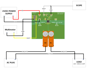
I am powering the EVM with a +5VDC power supply at VS but I am not seeing any change on the output side when measuring with a multimeter and I am getting what is to me odd results with a scope( See attached scope shots).
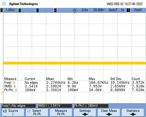
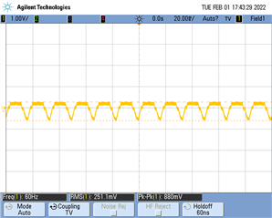
- With all components OFF (NO POWER):
- I read 25.1mV with multimeter,
- and with the scope, I read a pktopk voltage of 880mV
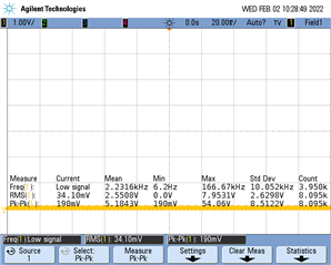
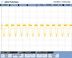
- With ONLY the DC Power Supply ON(+5VDC) and load OFF:
- I read 2.474V with a multimeter,
- and with the scope, I read a pktopk voltage of 2.13V
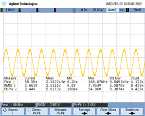
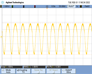
- With PS ON(+5VDC) and the load ON:
- I read 2.474V with a multimeter,
- and with the scope, I read a pktopk voltage of 4.38V
My Questions/Confusion:
- I thought the output should be a DC value, why do I see a sin wave with the scope -- this would imply to me that I'm seeing an AC signal?...
- Why are my multimeter readings the same with the load in ON state and OFF state? The lamp is rated for 500W @120V, that's ~4Amps of current -- Using the A3B EVM, I should see at least an 800mV change with that much current, right?..
Am I doing something wrong or not understanding something completely?
Thanks in advance for any help!