Other Parts Discussed in Thread: IWR1443
Hi,
I am using DCA1000EVM and IWR1443 to collect the raw data with mmWave studio 1.0.0.0 because of the old version of IWR1443. It works well but I have some question about the MIMO management.
Based on the figure, there are two types of MIMO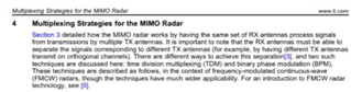
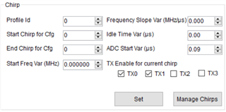
time division and binary phase modulation. I would like to use this ADC to collect the data of 3 transmitters and 4 receivers. Based on the raw data, I want to calculate the FFTs and get the estimated points. The question is that I don't know where to set the radar works under the time division mode with mmWave studio. In other words, when I got the data with 3 transmitters four receivers, I don't know the order of chirps for each receiver: the chirp is sent one by one from TX1, TX2, TX3, TX1.... or the three transmitters send the chirp at the same time.
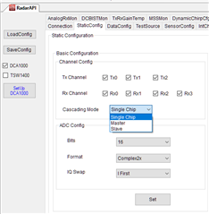
By the way, I also don't know how the cascading mode works. What is the meaning of Single Chirp mode, Master mode and Slave mode? Furthermore, are there any document to introduce the mmWave studio?
Thanks,
Wu