


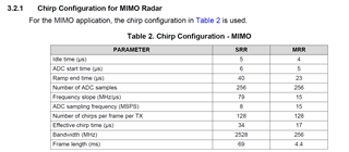
Other Parts Discussed in Thread: AWR2243, , MMWCAS-DSP-EVM, TIDEP-01012
Hi TI,
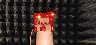
I am currently using a system, MMWCAS-RF-EVM (AWR2243) with the MMWCAS-DSP-EVM. I conducted an experiment whereby I wanted to test the accuracy of the height (vertical) discrimination of the system with the MIMO mode.
Here is the setup:
The configuration settings were taken from Design Guide: TIDEP-01012: Imaging Radar Using Cascaded mmWave Sensor Reference Design.
Both the MRR and SRR MIMO settings were used as shown in table 2: (All the parameters were followed and the only exception was that I did not program in the frame length, as I was not sure on how to do that, maybe you could provide some insight on this?)
Both Master and Slave have 10 frames each.
MRR
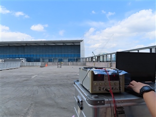
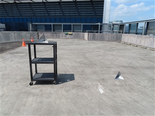
The distance to the target was approximately 20m. In order to test the vertical discrimination of the target, 2 tests were done. The first is shown below. The distance between CRs (lengthwise) is approx 2.5m.
(setup 1)
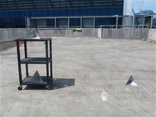
The second test (setup 2) is by adding a 2nd CR at the bottom of the cart as shown below: The CRs have approximately a distance of 1m (height-wise) between them.
I've run Matlab sample code cascade-MIMO_signalProcessing (note that I am using the default calibration file, i.e. no calibration was done). Although the range profile did show a return for both test setups at the correct distance, it seems that the height discrimination was not effective (by viewing the 3dpoint cloud) whatsoever. (Note that the Axis of the 3d point cloud were limited in order to filter out any unwanted dots)
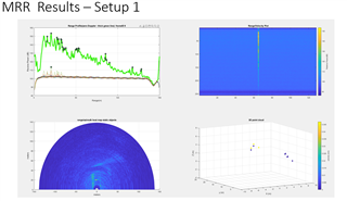
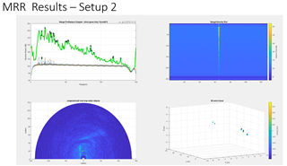
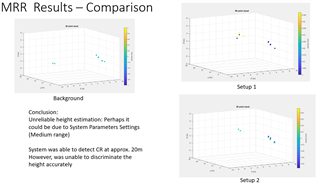
By using the 3d point cloud, I was not able to really decern any height discrimination. (note that the background capture in MRR-Results Comparison was taken without any CRs present. just the cart itself)
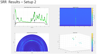
The second test (SRR Parameters), was performed in the exact same way with only 2 differences.
1. The CRs were at a much closer distance to the system (approx 9m.) i.e distance from the system to target was approx 9m.
2. The CRs were placed closer together (lengthwise), approx 1.5m
However this time, there was some height discrimination.
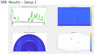
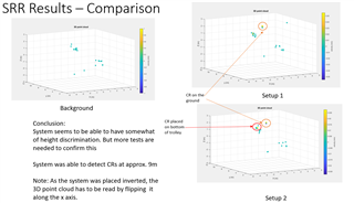
As the System was placed inverted, (something like this)
I've noticed that the 3D point cloud has to be read by flipping it along the x-axis.
Hence,
With regards, to the system, I noticed that it has good azimuth discrimination, however,
1. what are the factors that lead to height discrimination. Do the system parameters (start freq, stop freq, chirp rate) play a part in this?
2. Would it be possible to get any height discrimination at mid-range i.e. 50 to 100m?. If so, how can this be done and what can I expect the height discrimination to be?
3. What about Tx beamforming, will that help with height discrimination?
Your help is much appreciated. Thank You!
