This thread has been locked.

If you have a related question, please click the "Ask a related question" button in the top right corner. The newly created question will be automatically linked to this question.

MMWAVEICBOOST: CAN/SPI Hardware changes

Part Number: MMWAVEICBOOST
Other Parts Discussed in Thread: AWR6843ISK

Hi e2e,

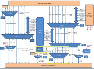
I am using the AWR6843ISK with MMWAVEICBOOST for my use-case that requires both SPI1and CAN. From the schematic of the MMWAVEICBOOST board, it appears that the CAN and SPI1 are muxed on the same line and toggled between using the dip switch(S1.1).

What are the necessary hardware changes that need to be done on the EVM to be able to get the output lines of both CAN and SPI1 to be able to use them simultaneously?

Thanks and regards,

KG

  • Hello Kaushik Gowda,

        In the 6843 SPI and CAN IPs are pin multiplexed in the design. Typically SPI and CAN are used as host interface, Automotive use cases CAN interface and non-Automotive interfaces uses SPI as host interface. These two interfaces are not used simultaneously, hence pin muxing is done on the I/O interface hence same is implemented in the  MMWAVEICBOOST as well.  Please review the pin muxing tool or pinmuxing section in the datasheet. 

    Thanks and regards,

    CHETHAN KUMAR Y.B.