This thread has been locked.

If you have a related question, please click the "Ask a related question" button in the top right corner. The newly created question will be automatically linked to this question.

AWR1642: Debugging Problem

Part Number: AWR1642
Other Parts Discussed in Thread: , TIDA-020004

Hello e2e,

I am working on our  custom design board, it has AWR1642.

Desing is same with TI AWR1642BOOS board.

Only difference is our desing supply voltage 12V.But all the necessary voltages are OK we get them.

The problem is about debugging.

I import srrdemo_16xx_dss and srrdemo_16xx_mss projects from project explorer.

And I also have TI AWR1642BOOS board.

I can debug these codes with TI AWR1642BOOS board.

I haven't maneged to debug with our board yet.

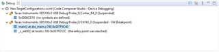
If I press "Test Connection" button at the target configuration file it says no error.And seems same with launchpad.

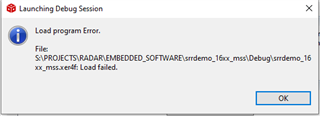
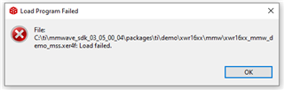
When press debug compiler gives "Load Program Error"


I want to add that I change SOP pins status as this for debug

SOP2 -> 1 

SOP1-> 1 

SOP0 -> 0

 with this config I can debug with launchpad.

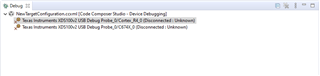
And I have used both XDS100v2 and XDS110 debuggers.

  • Hi,

    First, you need to make sure that the SOP pins are set as described in the AWR1642BOOST EVM User Guide.

    Are you able to connect the DSS and MSS cores?

    Do you have additional information about the Error?

    Thank you

    Cesar

  • Hi Cesar

    I add screenshots to show current status.

    Here is the error I get when debug fails.

    ERROR

    And this is the console log

     Console Log

    Here is test connection result

    Here is the mss and dss debug configs

    Please check and give me a feedback.

    Best Regards.

    EMRE

  • Have you tried loading the mmWave SDK demo pre-built binaries provided in:

    C:\ti\mmwave_sdk_03_05_00_04\packages\ti\demo\xwr16xx\mmw\xwr16xx_mmw_demo_mss.xer4f

    Thank you

    cesar

  • Hi Cesar,

    I follow the manual debug steps.here is the screenshots.

    first I go to "target configurations" and  "launch selected configuration" then the debug log is this

    then connect both cores 

    then load program to dss and it is succesfully enter main function

    then load program to Mss But MSS core gives error.I also try to load program to MSS first but it gives error again.

    Here is the error logs.

    Thanks

    EMRE

  • Hi,

    I would ask the HW team to review this thread

    thank you

    Cesar

  • One more question from me,

    I assume you have a flash on your board. Are you able to flash to it?

    Using CCS requires to flash the ccsdebug application.

    However, I don't think this is the issue here. I think that the chip is not powered properly

    thank you

    Cesar

  • Hello,

    Did you add a pre-regulator or change the PMIC? The PMIC used on AWR1642BOOST can only support up to 5.5V input, it will not work with 12V. If you did not change this to be able to support your 12V input then it will not work.

    Regards,

    Adrian

  • Hello Adrian,

    We used  TIDA-020004 design because it is a automotive design and suits our design goal.

    We copy almost all design only a few component changes.

    QSPI FLASH changes with competiable one.

    CAN-FD 2 is removed.

    These are all changes.

    Thanks.

    EMRE

  • Ok, that should work with 12V. Just to confirm, can you probe the supplies and make sure you are seeing the expected voltage:

    Also, can you check the voltage on the VBGAP pin after powering on?

    Lastly, please confirm Cesar's question regarding if you are able to successfully flash or not.

    Regards,

    Adrian

  • Hello Cesar,

    MX25R1635FZUIH0 this is our flash chip.

    Are you able to flash to it?

    I don't know,How can I check this?

    Thanks.

    EMRE

  • Hi Adrian,
    I can comfirm all of the voltage at above 1st picture is correct.


    And one of our boards VBGAP voltage is 0 now.But at the eval board it is 0.8V.There is a difference in this matter.

    i have a second board when i check it i confirm all voltages are correct including in VBGAP it is 0.89V.

    So I will check 1st card again.

    Now,

    All SOP voltages and supply voltages are same with launchpad with our 2nd board.

    I can not enter manual debug  with this board.

    Here is the error Log

    Cortex_R4_0: Trouble Writing Memory Block at 0x0 on Page 0 of Length 0x3c: (Error -1065 @ 0x0) Unable to access device memory. Verify that the memory address is in valid memory. If error persists, confirm configuration, power-cycle board, and/or try more reliable JTAG settings (e.g. lower TCLK). (Emulation package 9.4.0.00129)
    Cortex_R4_0: File Loader: Verification failed: Target failed to write 0x00000000
    Cortex_R4_0: GEL: File: S:\PROJECTS\RADAR\EMBEDDED_SOFTWARE\srrdemo_16xx_mss\Debug\srrdemo_16xx_mss.xer4f: Load failed.

    Thanks,

    EMRE

  • Hello Adrian,

    Is there any update about this topic.

    Thanks

    EMRE